
Chatter in surface grinding usually appears as a repeating pattern, waviness, or periodic finish variation, but the mark alone does not identify the source. Vibration may enter through the wheel, spindle, workholding, machine structure, or surrounding environment; the grinding process can also amplify a small disturbance. Diagnose it by mapping the pattern, checking whether it repeats with wheel or workpiece rotation, and reviewing the last controlled change to dressing, setup, or operation sequence.
This article focuses on surface grinding, where a flat workpiece and wheel interact across a defined contact zone. It is different from centerless-grinding troubleshooting: the support geometry, workholding, and likely signal paths are not interchangeable.
Map the mark before touching the wheel
Start with a photograph and a simple record of the ground face. Note the direction of visible marks relative to the table travel and wheel rotation, whether the pattern is uniform or localized, and whether it changes near an edge, slot, or thin section. Compare the observation with the previous accepted part and the drawing’s surface and flatness requirements.
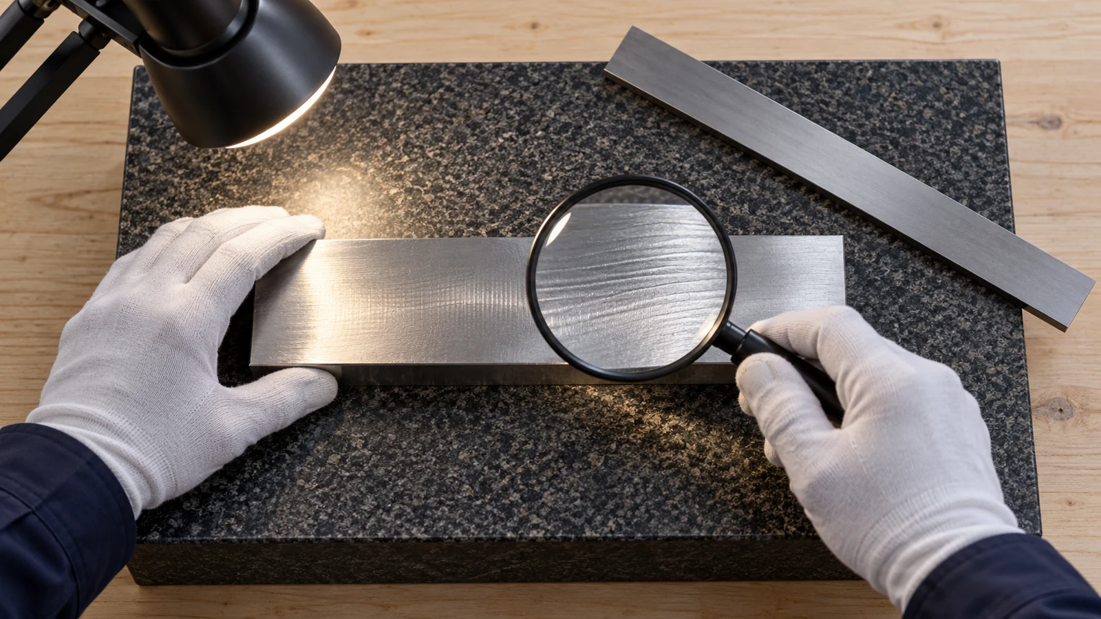
| Pattern or timing | First area to inspect | What the check helps separate |
|---|---|---|
| Regular bands across much of the face | Wheel balance, mounting, spindle condition, table or nearby vibration | Periodic machine or wheel excitation |
| Marks become stronger after dressing | Dresser condition, dressing setup, wheel face and subsequent engagement | Dressing-related surface or vibration change |
| Defect concentrated at a thin edge or unsupported area | Magnetic or mechanical holding, support, local stiffness | Workpiece motion or distortion |
| Finish changes gradually during a run | Wheel loading, wear, coolant delivery, material variation | Process drift rather than a single transient |
| Pattern appears after nearby equipment starts | Floor, foundation, adjacent machinery, enclosure or coolant system | External vibration entering the setup |
Do not infer a specific frequency or machine fault from visual spacing without a measurement method. A surface pattern can be affected by wheel speed, table motion, workpiece movement, dressing marks, and image scale. If a vibration analyzer or accelerometer is used, record where it is mounted and under what operating condition.
Check the wheel, machine, and workholding
Inspect the wheel and mounting first. Confirm that the wheel is appropriate for the material and operation, correctly mounted, in good condition, and dressed using a stable procedure. Loading, glazing, uneven wear, damage, or eccentricity can alter the contact and the forces. Follow the wheel maker’s safety requirements and shop procedures; never assume a dressing adjustment is safe merely because it improves appearance.
Check the machine path next. Verify that guards, fixtures, workholding, and table travel are secure. Look for loose interfaces, contamination on the magnetic chuck or workpiece, and a part that rocks or bridges over debris. A small piece of swarf beneath a thin workpiece can change how it is supported. Where the work is flexible, clamping or magnetic force can also change its free-state shape; a surface that looks flat while held may move after release.
Then review coolant and chip control. Delivery should reach the contact zone consistently, and the coolant condition should be suitable for the process. A disturbed flow, clogged filter, or wheel loading may change grinding behavior during the run. These checks should be recorded alongside the surface pattern so a correction can be linked to an observed cause.
Use dressing as a controlled test
Dressing restores or conditions the wheel face, but it should not be used as a random adjustment knob. Record the dresser type and condition, setup, traverse direction, and the sequence between dressing and grinding. If the chatter pattern changes immediately after a dressing operation, that is useful evidence; if it does not, repeated dressing may consume wheel and part stock without addressing a mounting, workholding, or environmental issue.
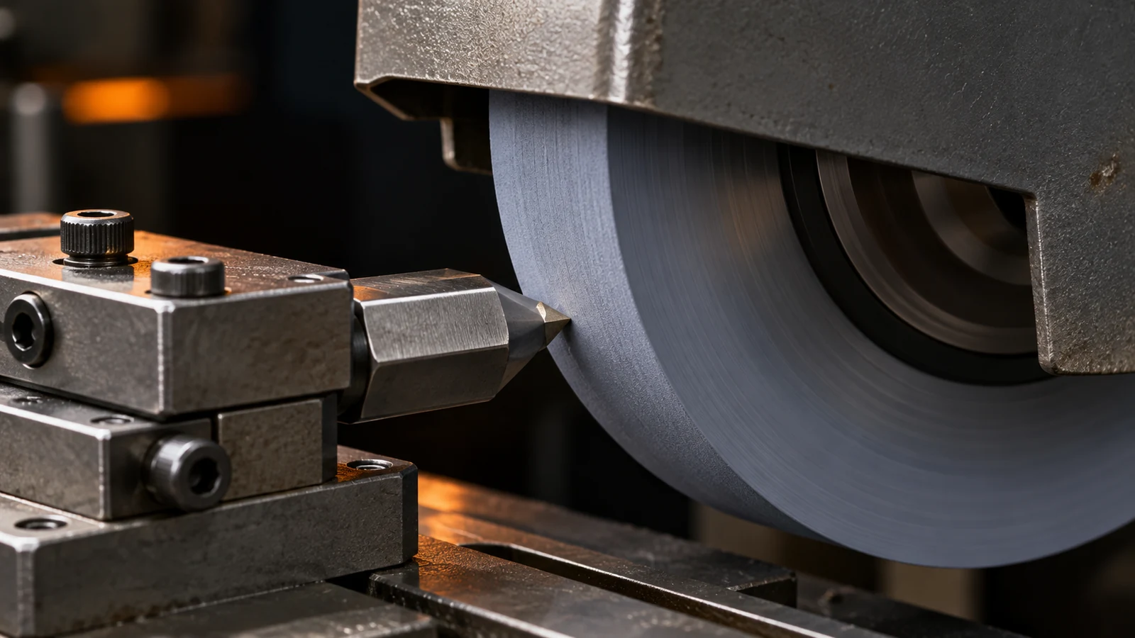
- Hold the part, wheel, coolant, and grinding route constant for the comparison.
- Record the ground face and the relevant dimensional result before changing the dressing procedure.
- Change one dressing variable within the approved process and inspect the same region afterward.
- Check wheel condition and part support if the pattern remains or returns quickly.
- Escalate persistent vibration for machine or process diagnosis rather than compensating with undocumented settings.
Surface grinding is a finishing route, not a guarantee that every geometry or material will respond the same way. For related process context, see the site’s surface grinding capability and precision grinding overview. The correct approach depends on the part, stock condition, wheel specification, machine, and inspection plan.
Connect the finish to the part requirement
Not every visible ripple has the same functional significance. A ground datum, sliding face, sealing surface, or bearing interface may require a defined surface texture, flatness, parallelism, or relationship to another feature. A nonfunctional area may not require the same level of control. State the requirement on the drawing or purchase specification, and make sure the method used to verify it matches the characteristic.
For supplier review, share the drawing revision, material and hardness condition, stock allowance, ground surfaces, datum scheme, finish requirement, and quantity. If the question is a process problem, include the pattern location, when it first appeared, and any recent wheel or setup change. That information allows the cause to be traced without promising a universal wheel grade, dressing value, or table speed.
Frequently asked questions
Will dressing always remove surface-grinding chatter?
No. Dressing may help when wheel condition or the dressing process is involved. It will not correct a loose setup, workpiece movement, spindle problem, or vibration transmitted from nearby equipment.
Can chatter marks be confused with grinding burn?
Yes, visual defects can overlap, but chatter is a vibration-related pattern while burn involves thermal damage. A proper evaluation may require surface inspection and, for critical parts, a suitable method to assess material integrity.
Should the supplier set a universal chatter limit?
No. Acceptance should be tied to the drawing’s functional requirement, surface specification, and inspection method. A vague visual limit can lead to different interpretations by the supplier and buyer.