
Machining Teflon looks simple until dimensional accuracy becomes part of the drawing. PTFE is soft, chemically resistant, naturally lubricious, and relatively easy for a sharp cutting tool to remove. Yet those same characteristics make the material difficult to hold, measure, and control. A component may leave the CNC machine within specification and then change slightly after clamping pressure, cutting heat, or internal stress is removed.
For engineers and purchasing teams, this creates a different sourcing problem from conventional metal machining. The question is not simply whether a supplier owns a CNC mill or lathe. The better question is whether that supplier understands how PTFE behaves before, during, and after material removal.
This buyer’s guide explains how CNC-machined PTFE parts are produced, what tolerances may be practical, how turning compares with milling, how speeds and feeds should be approached, what safety issues matter, and how to evaluate a machining supplier for prototypes and production parts.
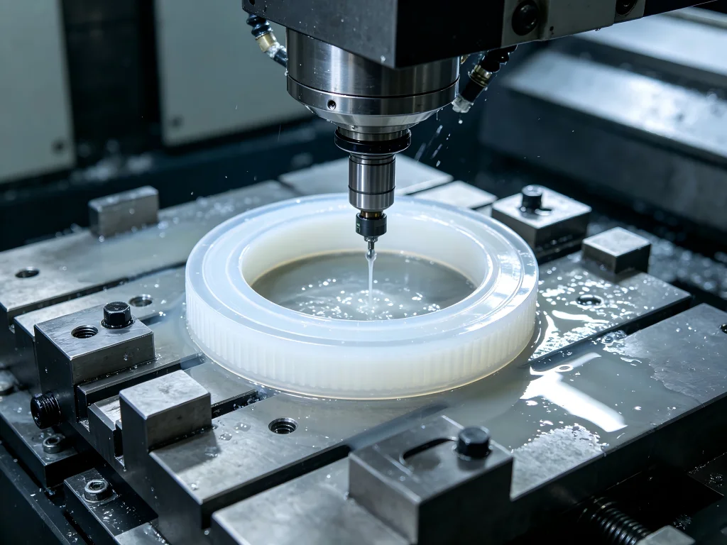
Can Teflon Be Machined?
Yes. Teflon, commonly used as a trade name associated with PTFE, can be machined using conventional CNC equipment. Turning, milling, drilling, boring, grooving, threading, facing, and other subtractive operations may all be used to manufacture PTFE components.
The important distinction is that PTFE should not be treated like aluminum, steel, or even every other engineering plastic.
Its low friction is one of its greatest functional advantages, but it also makes workholding more difficult. Its softness helps tools cut through it with relatively low cutting forces, yet excessive clamping pressure may distort the workpiece. Its temperature resistance makes PTFE useful in demanding applications, while its comparatively high thermal expansion makes precision measurement and dimensional control more challenging.
This explains a common observation among machinists: PTFE can be easy to cut but difficult to hold to demanding geometry.
A reliable process therefore depends on controlling several variables together:
- Material grade and stock condition
- Tool sharpness and cutting geometry
- Workholding pressure
- Cutting temperature
- Chip evacuation
- Part geometry
- Machining sequence
- Inspection temperature
- Time allowed before final measurement
Ignoring any one of these factors may turn an apparently simple plastic component into a difficult tolerance problem.
PTFE vs Teflon: What Should Buyers Specify?
Buyers frequently use “Teflon” and “PTFE” as interchangeable terms, but engineering documentation should be more precise.
PTFE stands for polytetrafluoroethylene. Teflon is a well-known trademark associated with fluoropolymer products. When preparing an RFQ, purchasing specification, or engineering drawing, identifying the exact polymer grade and material requirement is more useful than relying only on a generic commercial name.
This becomes especially important when filled or modified PTFE grades are involved.
Virgin PTFE may provide outstanding chemical resistance, low friction, electrical insulation, and broad temperature capability. Filled PTFE materials may incorporate substances such as glass, carbon, graphite, or other fillers to modify wear behavior, stiffness, creep resistance, or dimensional characteristics.
Consequently, two parts that look identical on a drawing may behave differently during machining and service if their material grades differ.
Why Is CNC Machining PTFE More Difficult Than It Looks?
Imagine a purchasing engineer sourcing a sealing component. The drawing appears straightforward: a round PTFE part with an internal bore, sealing face, groove, and several controlled diameters.
Three suppliers quote it.
The first treats it like a standard plastic turning job. The price is low.
The second raises concerns about the tolerance and recommends changing the inspection method.
The third asks about operating temperature, mating components, PTFE grade, measurement conditions, and which dimensions are functionally critical.
The third supplier may appear more complicated during quoting, but those questions often indicate a better understanding of polymer machining.
PTFE creates several interconnected manufacturing challenges.
1. The Material Can Deform Under Clamping Pressure
A metal workpiece normally tolerates considerable jaw or collet pressure. PTFE requires more restraint.
Excessive chuck, vise, or fixture pressure may temporarily change the shape of the stock. A machinist could machine a diameter while the component is compressed, measure it in the fixture, and believe the dimension is correct. Once released, the component may recover toward its original shape.
This elastic recovery is one reason experienced shops pay close attention to soft jaws, larger contact areas, controlled clamping force, and machining sequence.
2. Heat Changes Dimensions
PTFE has a much higher coefficient of thermal expansion than many metals. Temperature changes that would have little practical effect on a steel component may become relevant on a precision polymer part.
Cutting heat, coolant temperature, room temperature, operator handling, and inspection timing may therefore influence measurement results.
For demanding parts, dimensional inspection should not be treated as an isolated final step. It should be integrated into the manufacturing process.
3. PTFE Has Low Rigidity
Thin walls, long unsupported sections, narrow sealing lips, deep bores, and slender rods may deflect under cutting or measuring forces.
This means a tighter tolerance does not automatically create a better component.
If the tolerance is much tighter than the application requires, manufacturing cost can rise sharply without delivering a meaningful functional advantage.
4. Burrs Can Become a Quality Problem
A dull cutting edge may push or tear the polymer rather than producing a clean slicing action. The result may include fuzzy edges, burrs, distorted features, or an unacceptable sealing surface.
This is why tool condition often matters more than simply increasing spindle speed.
Machining Teflon Methods Compared
| Method | Best Suited For | Main Advantage | Main Risk | Typical Buyer Concern |
|---|---|---|---|---|
| CNC Turning | Rings, bushings, seals, sleeves, washers and cylindrical parts | Efficient control of concentric features | Chuck deformation and stringy chips | Diameter, roundness and concentricity |
| CNC Milling | Plates, blocks, manifolds and non-round components | Flexible geometry and multi-face machining | Workpiece movement and wall deflection | Flatness, position and feature accuracy |
| Mill-Turn | Complex cylindrical parts with cross holes or milled features | Fewer setups | More demanding process planning | Relationship between turned and milled features |
| 5-Axis CNC | Complex multi-surface components | Reduced repositioning | May be unnecessary for simple geometry | Setup reduction and feature alignment |
| Manual/Secondary Machining | Simple modifications and deburring | Flexible for low-volume work | Operator-dependent consistency | Repeatability in production |
Machining Teflon on a Lathe
A CNC lathe is often the natural choice for round PTFE components. Typical products include valve seats, insulating rings, bushings, spacers, washers, sleeves, seals, bearing components, and fluid-control parts.
Successful machining Teflon lathe work depends heavily on workholding and tool geometry.
A sharp tool with suitable positive geometry may slice the polymer cleanly instead of pushing it away from the cutting edge. The machinist must also control how tightly the stock is held. Excessive pressure can distort the outside diameter or bore.
Another issue is chip formation.
Turning PTFE may produce long, continuous chips. These chips can wrap around the workpiece, tool, or chuck. Good programming, chip control, and safe machine operation are therefore important even though cutting forces are relatively low.
For long components, support also deserves attention. A slender PTFE rod may bend or whip more easily than a comparable metal bar. Bar feeding, guide bushings, support length, and machining sequence should be evaluated before production begins.
Machining Teflon Rod: Why Stock Shape Matters
Machining Teflon rod is common because many PTFE parts begin as extruded or molded cylindrical stock.
However, a buyer should not assume that every rod behaves identically.
Stock diameter, manufacturing method, material grade, residual stress, storage conditions, and part geometry may affect the finished result.
Suppose a finished component requires a thin wall after most of the original rod is removed. The original stock may appear dimensionally stable, but removing a large percentage of material can change the stress balance within the component.
A better process may use staged machining.
- Inspect the incoming material and confirm the correct grade.
- Rough-machine the major features while leaving controlled finishing allowance.
- Allow the component to stabilize when the geometry and tolerance justify it.
- Finish critical diameters, bores, sealing surfaces, and shoulders.
- Deburr using methods that do not distort soft edges.
- Allow the component to reach a stable inspection condition.
- Measure critical dimensions using appropriate low-force inspection methods.
This sequence may take longer than machining everything in one aggressive operation, but it can provide better control for demanding components.
Machining Teflon Speeds and Feeds: Why There Is No Universal Number
Searches for machining Teflon speeds and feeds often suggest that users want a single RPM and feed-rate formula. In practice, responsible process planning requires more information.
Suitable cutting conditions depend on tool diameter, cutting-edge geometry, machine capability, operation type, depth of cut, workholding, material grade, wall thickness, coolant strategy, surface requirement, and feature geometry.
That is why copying an RPM value from a forum can be misleading.
A 6 mm end mill machining a thin PTFE wall cannot be treated exactly like a large turning tool roughing a thick rod.
The better starting principle is to create a clean cutting action while limiting unnecessary heat and deformation.
Sharp Tools Come First
Machinists repeatedly emphasize sharp tooling when discussing PTFE. This practical experience makes sense because a sharp edge reduces the tendency to push, smear, or tear soft material.
A worn tool that might still produce an acceptable cut in another material may create poor edges on PTFE.
Do Not Confuse High Speed With High Productivity
Because PTFE cuts easily, it may be tempting to increase spindle speed aggressively. Yet productivity should be evaluated through total process stability rather than RPM alone.
If additional speed creates more heat, worsens dimensional consistency, increases chip-management problems, or damages the surface, the theoretical cycle-time improvement has little value.
Feed, spindle speed, tool engagement, chip load, and cooling strategy should work as a system.
Use Chips as Process Feedback
Good machining should remove material cleanly. If the polymer begins smearing, tearing, excessively heating, or forming problematic burrs, the cutting conditions and tool condition should be reviewed.
For a production supplier, the goal is not finding the fastest possible setting for one component. The goal is establishing a stable machining window that can repeatedly produce acceptable parts.
What Reddit Machinists Consistently Say About PTFE
Online machinist communities provide useful practical context when their comments are treated as shop-floor observations rather than formal engineering specifications.
Several recurring themes appear in machinist discussions about PTFE.
First, machinists repeatedly emphasize extremely sharp cutting edges. Operators describe the difference between cleanly “slicing” PTFE and pushing or tearing it with a worn edge.
Second, workholding receives almost as much attention as cutting parameters. Users frequently discuss PTFE slipping in a vise or deforming under pressure. Some machinists use serrated jaws, specialized soft jaws, increased contact area, or other workholding strategies that allow adequate grip with less crushing force.
Third, experienced operators often warn that achieving the dimension while the component is clamped is not the same as guaranteeing the dimension after release.
Fourth, long string-like chips are a repeated topic in turning discussions. The material may cut easily while still requiring deliberate chip management.
These comments point toward an important purchasing lesson: PTFE machining experience is often more valuable than raw spindle speed.
Teflon Machining Tolerances: How Tight Is Realistic?
Teflon machining tolerances should be determined by component function, geometry, size, PTFE grade, and inspection conditions rather than copied from a metal-machining drawing.
PTFE’s softness, creep behavior, thermal expansion, and low stiffness can make narrow tolerance bands challenging, particularly for large parts, thin walls, flat plates, long unsupported features, and components with substantial material removal.
Specialist engineering-plastic manufacturers also identify PTFE’s high coefficient of thermal expansion and comparatively low mechanical strength as major considerations when specifying narrow machining tolerances.
Therefore, the best drawing is usually not the drawing with the most decimal places. It is the drawing that clearly distinguishes functional dimensions from non-critical dimensions.
Use Functional Tolerancing
Consider a PTFE valve seat.
The sealing face, bore, and relationship to the mating diameter may have direct functional importance. An external non-mating surface may not need the same tolerance.
If every dimension receives an unnecessarily narrow tolerance, machining and inspection become more expensive without improving the assembly.
Engineers should identify:
- Critical sealing dimensions
- Mating diameters
- Concentric relationships
- Critical thicknesses
- Flatness or parallelism requirements that affect function
- Non-critical clearance dimensions
- Inspection temperature where relevant
- Whether dimensions apply in a free or assembled condition
This gives the manufacturer enough information to develop a rational machining process.
How Geometry Changes PTFE Machinability
A tolerance cannot be evaluated separately from geometry.
A relatively thick ring may hold a diameter more predictably than a thin, flexible ring. A short bushing may be easier to control than a long sleeve. A small plate may behave differently from a large thin sheet.
When reviewing an RFQ, a capable CNC supplier should therefore examine the complete tolerance stack rather than simply confirming each number individually.
Potentially difficult features include deep narrow grooves, very thin walls, long bores, small holes with high depth-to-diameter ratios, sharp unsupported edges, large flat surfaces, and closely controlled features separated by substantial material removal.
Design-for-manufacturing review may identify a small change that significantly improves repeatability.
Machining Teflon Dangers: What Is the Real Risk?
The phrase machining Teflon dangers attracts considerable search traffic because users often encounter conflicting information online.
It is important to separate normal controlled machining from overheating and thermal decomposition.
PTFE should not be deliberately overheated. At sufficiently elevated temperatures it can thermally decompose and generate hazardous decomposition products. Occupational health literature has associated exposure to PTFE thermal degradation products with polymer fume fever.
Normal CNC machining should therefore be planned to avoid excessive heat generation. Shops should use suitable tooling, appropriate cutting conditions, effective chip removal, machine guarding, housekeeping, and appropriate ventilation according to the process and workplace risk assessment.
Smoking should not occur in areas where PTFE contamination could transfer to cigarettes or smoking materials.
Operators should also avoid unsafe interaction with moving chips. Long continuous swarf may wrap around rotating components. Machine doors, guarding, chip-management routines, and established shop safety procedures should always be followed.
The practical lesson is simple: PTFE is a machinable engineering polymer, but “easy to cut” should never be interpreted as “no process controls required.”
Where Machined Teflon Parts Are Used
Machined Teflon parts appear in applications where low friction, electrical insulation, chemical resistance, sealing behavior, or temperature capability matter.
Fluid Handling and Valves
PTFE is widely considered for valve seats, seals, rings, bushings, spacers, and other components exposed to aggressive fluids.
Chemical resistance is a major advantage, while CNC machining allows sealing geometry and mating dimensions to be produced from stock material.
Semiconductor and Electronics Equipment
Electrical insulation and chemical resistance can make PTFE useful in components for electronics and processing equipment.
In these applications, contamination control, dimensional consistency, material documentation, and clean handling may matter as much as the machining operation itself.
Medical and Laboratory Equipment
PTFE may be selected for certain laboratory, analytical, fluid-control, and equipment components where its material characteristics fit the application.
Material selection should always follow the regulatory and functional requirements of the final device rather than assuming that a polymer is automatically suitable because of its general properties.
Industrial Equipment
Wear strips, guides, insulators, spacers, low-friction components, bushings, and seals are common industrial examples.
Automotive and Transportation Systems
PTFE may be used in specialized seals, insulating components, guides, and fluid-handling applications where its friction and chemical characteristics provide an advantage.
CNC Machining Teflon vs POM, Nylon and PEEK
Choosing PTFE should begin with the application rather than the machining process.
If chemical resistance and extremely low friction dominate the requirement, PTFE may be attractive. If stiffness and dimensional stability are more important, another engineering polymer could sometimes provide a better balance.
POM, for example, is often selected where dimensional stability, stiffness, low friction, and good machinability are required.
Nylon offers useful strength and wear characteristics but moisture absorption may influence dimensions and properties.
PEEK provides considerably higher mechanical performance for demanding applications, although material cost is much higher and machining considerations differ.
PTFE should therefore not be selected simply because it is familiar. A competent machining supplier may help buyers compare material behavior before production tooling and inspection plans are finalized.
How to Choose a Teflon Machining Supplier
A search for teflon machining near me may produce dozens of machine shops. Distance, however, is only one procurement factor.
For a simple one-off spacer, a local general machine shop could be sufficient. For repeat production, critical sealing geometry, international sourcing, documented inspection, or complex parts, process experience may matter more than geographic distance.
1. Ask About Polymer Experience, Not Just CNC Equipment
A five-axis machining center does not automatically make a company an expert in PTFE.
Ask what engineering plastics the supplier regularly machines, how it controls deformation, what workholding approaches it uses, and how it inspects flexible components.
2. Review Inspection Capability
Inspection equipment matters, but the inspection method matters equally.
A measurement system designed around rigid metal components can produce misleading results if excessive contact force deforms a soft polymer feature.
The supplier should understand the relationship between measuring force, temperature, fixture condition, and dimensional stability.
3. Examine Quality Systems
For B2B sourcing, certification can provide evidence that documented procedures exist for quality control, traceability, corrective action, and process management.
The relevance of a specific certification depends on the industry and project.
4. Evaluate DFM Support
The best supplier may sometimes challenge the drawing.
If a machinist identifies an unrealistic tolerance, fragile wall, difficult groove, or inspection conflict before production, that feedback can prevent scrap and delays.
Good DFM is not a request to lower quality. It is a way to align design intent with manufacturable geometry.
5. Compare Total Cost, Not Piece Price
A low quotation becomes expensive when parts require sorting, rework, replacement, or emergency freight.
Buyers should consider first-pass yield, inspection documentation, communication, engineering support, repeatability, packaging, lead time, and supply reliability alongside the quoted unit price.
Why Jucheng for CNC-Machined PTFE Parts?
Jucheng Precision provides CNC machining services for metals and engineering plastics, with PTFE included among the plastic materials listed in its manufacturing capabilities.
This broad machining base matters because many B2B projects are not isolated PTFE components. An assembly may combine PTFE seals or insulators with aluminum housings, stainless-steel shafts, brass fittings, POM components, or other machined parts.
A supplier able to work across multiple materials may simplify sourcing and dimensional coordination.
Multi-Process CNC Capability
Depending on component geometry, Jucheng can apply CNC turning, CNC milling, combined mill-turn processes, and multi-axis machining strategies.
This provides flexibility when a component combines rotational features with cross holes, pockets, slots, or multi-face geometry.
Reducing unnecessary setups can also help maintain relationships between features because fewer manual repositioning operations are required.
Inspection Infrastructure
Jucheng’s published manufacturing information describes quality inspection using advanced measuring equipment, including Zeiss CMM systems.
For PTFE, sophisticated equipment should still be combined with an appropriate inspection strategy because soft polymers can respond to contact pressure and temperature differently from metals.
Quality Certifications
Jucheng publishes quality credentials that include ISO 9001:2015, ISO 14001, ISO 13485, and IATF 16949.
For buyers in automotive, medical equipment, industrial, and other controlled supply chains, documented quality systems can be an important part of supplier qualification.
Prototype-to-Production Support
PTFE components often benefit from prototype validation before volume manufacturing.
A prototype can reveal whether the drawing tolerance reflects actual assembly needs, whether a thin feature distorts after machining, whether a sealing surface requires adjustment, and whether the selected PTFE grade provides the expected behavior.
Once those variables are understood, the machining and inspection process can be standardized for production.
Learn more about Jucheng’s CNC machining capabilities or submit drawings for engineering review and quotation.
A Practical RFQ Checklist for Machined PTFE Parts
A detailed RFQ can shorten quotation time and reduce assumptions. Buyers should ideally provide a 3D CAD model together with a controlled 2D drawing.
The package should clearly communicate material grade, quantity, critical tolerances, surface requirements, inspection expectations, and end-use conditions where those conditions affect manufacturing.
For example, telling a supplier that a diameter forms a chemical-service sealing interface is more informative than simply assigning a narrow tolerance without context.
Also identify expected annual volume. A process optimized for five prototype pieces may differ from one intended for 50,000 production parts.
Installation and Maintenance of Machined PTFE Components
Machining quality can be lost during assembly if PTFE parts are handled like rigid metal components.
Before installation, inspect sealing surfaces and critical edges for shipping damage, contamination, or deformation. Components should be stored in conditions appropriate for the material and application.
During assembly, avoid unnecessary point loading. Thin rings and sealing lips can deform if forced into position with inappropriate tools.
Fasteners should be tightened according to the assembly design rather than simply applying maximum available torque. PTFE can creep under sustained load, so joint design should account for the material’s long-term behavior.
Maintenance schedules should reflect the actual operating environment. Temperature, pressure, chemical exposure, sliding contact, cycle count, and mating-surface condition may all influence service life.
Real-World Case Example: Precision PTFE Valve Seat
Consider a hypothetical fluid-control manufacturer developing a new valve assembly.
The original drawing specifies a PTFE seat with a tight outside diameter, precision bore, sealing angle, narrow groove, and thin final wall. The first purchasing approach focuses entirely on finding the lowest machining quotation.
During prototype production, the outside diameter appears acceptable while clamped. After the parts are released and inspected later, several measurements shift. The sealing face also shows inconsistent edge quality.
A process-focused review identifies three possible causes: excessive workholding pressure, insufficiently sharp finishing tools, and measurement before the components had reached a consistent thermal and mechanical condition.
The revised process uses more appropriate workholding, separates roughing from final finishing, controls the finishing allowance, uses sharp tooling, and standardizes the inspection procedure.
The important point is not that every PTFE valve seat needs exactly this process. It is that PTFE quality comes from controlling the complete manufacturing chain rather than relying on one tolerance value or one CNC setting.
Buyer Decision Framework: Local Shop or Specialist CNC Partner?
A local supplier may be the right choice when the component is simple, tolerance requirements are moderate, volume is low, and rapid face-to-face support is valuable.
A specialist manufacturing partner becomes more attractive when the project involves complex geometry, multiple materials, demanding inspection documentation, recurring volume, international supply requirements, or industry-specific quality systems.
The sourcing decision should therefore consider risk as well as distance.
For repeat production, ask the supplier how the process will remain consistent six months after the first approved batch. Tool control, material traceability, setup documentation, inspection planning, and revision control may become more important than the initial prototype cycle time.
Frequently Asked Questions About Machining Teflon
Can Teflon be machined?
Yes. PTFE can be CNC turned, milled, drilled, bored, grooved, and otherwise machined using conventional equipment. The main challenges are dimensional stability, deformation, workholding, burr control, heat management, and inspection rather than basic material removal.
Is Teflon easy to machine?
It is relatively easy to cut because cutting forces can be low, but producing repeatable precision parts may be more difficult. Its softness, low rigidity, low friction, creep behavior, and thermal expansion require a process designed specifically for the material.
What are good speeds and feeds for machining PTFE?
There is no universal value. Suitable parameters depend on tool geometry, operation, stock size, machine, PTFE grade, depth of cut, wall thickness, workholding, and cooling strategy. Sharp cutting edges and temperature control should normally take priority over simply maximizing RPM.
What tolerances can be held on machined Teflon?
Achievable tolerance depends strongly on part size, geometry, material grade, wall thickness, temperature, and inspection method. Tight dimensions may be possible on suitable features, but applying metal-like tolerances indiscriminately can increase cost and reduce process capability. Critical tolerances should be reviewed with the manufacturer.
Is machining Teflon dangerous?
Controlled machining is a standard industrial process, but PTFE should not be excessively overheated. Thermal decomposition at elevated temperatures can produce hazardous fumes. Appropriate cutting conditions, ventilation, housekeeping, machine guarding, chip control, and workplace safety procedures should be used.
What tools are best for machining PTFE?
Sharp tools with geometry suitable for clean cutting are generally preferred. Exact tool selection depends on whether the operation involves turning, milling, drilling, boring, grooving, or threading. Tool condition is especially important because dull edges may push or tear the soft material.
Why do PTFE dimensions change after machining?
Possible causes include thermal expansion, elastic recovery after clamping, residual stress, material creep, measurement force, and changes in temperature. This is why difficult components may benefit from staged machining and controlled inspection conditions.
Should I choose CNC turning or CNC milling for PTFE?
Turning is generally efficient for cylindrical parts such as bushings, rings, valve seats, and sleeves. Milling is better suited to plates, blocks, pockets, and non-rotational geometry. Components containing both types of features may benefit from mill-turn or multi-axis machining.
Final Buying Advice
The central lesson of PTFE machining is easy to remember: easy cutting does not equal easy precision.
A successful supplier must manage material behavior, tool sharpness, workholding, heat, chip formation, machining sequence, dimensional recovery, and inspection as one connected process.
For procurement teams, this changes how suppliers should be compared. The cheapest hourly machining rate or the closest machine shop may not deliver the lowest total manufacturing cost. Process knowledge, DFM support, quality documentation, inspection capability, and repeatability should carry substantial weight.
For engineers, the greatest opportunity often comes before the first chip is cut. Clearly identifying functional tolerances, material grade, mating conditions, inspection requirements, and operating environment can eliminate unnecessary manufacturing difficulty.
If your project requires custom PTFE seals, bushings, valve components, insulating parts, rings, sleeves, spacers, prototypes, or other precision polymer components, Jucheng can review your CAD files and drawings before production.
Visit Jucheng Precision CNC Machining to explore machining capabilities or request a project review. Providing the 2D drawing, 3D model, material requirement, quantity, and critical dimensions can help the engineering team evaluate manufacturability and prepare an appropriate machining strategy.
Authoritative Technical References
For additional information about PTFE machining behavior and occupational safety, engineering teams may consult specialist polymer-machining resources and government occupational-health guidance.
Ensinger PTFE Machining Technical Information discusses the influence of PTFE’s low strength and high thermal expansion on narrow machining tolerances.
NIOSH provides occupational-health information concerning fluoropolymer thermal decomposition and polymer-fume exposure. These sources should be used together with the material manufacturer’s current safety data sheet and the machining facility’s own risk assessment.