
Plunge milling is worth considering when a deep pocket, long tool overhang, or limited setup rigidity makes radial side cutting the main source of deflection or chatter. The cutter advances primarily along its axis, so the process can shift much of the cutting load toward axial compression. That advantage is conditional: chip evacuation, tool geometry, spindle capability, entry clearance, and the remaining wall stock still determine whether plunging is a sound roughing route.
For an open, shallow pocket on a rigid setup, side milling or an adaptive toolpath is often simpler and may leave a better wall for finishing. The useful question is not whether plunge milling is “stronger,” but whether changing the force direction solves the actual constraint in this feature.
Why force direction matters in a deep pocket
During side milling, the cutter is pushed laterally while its overhang acts like a lever. As reach increases, small changes in engagement, tool stickout, holder condition, or workholding can produce visible deflection and vibration. A plunge cut changes the dominant load direction: instead of asking a slender tool to carry the whole roughing force sideways, the tool advances into the material axially.
That does not remove cutting force or guarantee a chatter-free result. The tool, holder, spindle, workpiece, and fixture still form one system. Axial force must be supported by the machine and tool assembly, and the selected cutter must be designed for the intended plunging operation. A standard end mill should not automatically be treated as a plunge cutter; center-cutting geometry, chip space, and the tool maker’s application guidance matter.
This is one option within a broader CNC machining process plan. The route should be chosen around the feature, datum strategy, stock condition, and finishing requirements—not around a toolpath name in isolation.


Where plunge milling fits—and where it does not
Plunge roughing is most promising when the pocket is deep relative to the cutter diameter, the tool must reach past a tall wall, or a narrow cavity limits the safe radial engagement available to a side-cutting tool. It can also help when a part’s geometry or clamping arrangement makes lateral loading especially sensitive. In those cases, the first comparison should be between the current force problem and the axial-load capacity of the complete setup.
It is less compelling when the cavity is shallow and open, the tool has short reach, or the floor and walls require a high-quality finish directly from the roughing operation. A plunge strategy may leave scallops or a stepped floor that requires a separate cleanup path. It can also be a poor choice when the chips cannot leave the cavity reliably or when the machine cannot execute the required retract and reposition cycle efficiently.
Before selecting the method, distinguish three separate objectives: bulk stock removal, wall/floor finishing, and corner cleanup. One strategy does not need to perform all three. A robust plan may use plunging only to remove material from the deepest zone, then switch to side milling for accessible walls and a controlled finishing pass.
Plan entry, overlap, and chip flow
Toolpath design begins with a safe entry point. The programmer needs to know whether the tool can enter solid stock, whether a pilot opening or pre-drilled relief is appropriate, and how the cutter will clear the pocket boundary without striking a wall or clamp. These choices depend on the part and tool; there is no universal entry pattern.
Adjacent plunges need enough overlap to avoid leaving ridges that create uneven loads on the next path, but excessive overlap adds cycle time and may recut chips. The sequence should also avoid trapping chips beneath the cutter. In a deep cavity, coolant direction, air flow, tool flute space, and retract distance can be as important as the nominal cutting parameters. If chips recirculate, the tool may re-cut them, damaging the edge or marking the surface.
Use the cutter manufacturer’s data as the starting point for speed, feed, depth, and engagement. Then evaluate the actual workpiece material, machine, holder, tool projection, coolant arrangement, and setup stiffness. A program that is stable in a short test block may behave differently when a thin wall or long reach changes the system rigidity.
Compare roughing routes before choosing
| Route | Useful when | Check before committing |
|---|---|---|
| Plunge roughing | Deep reach or radial deflection is the limiting concern | Plunge-capable cutter, axial load path, chip evacuation, floor cleanup |
| Side or adaptive milling | Tool reach is moderate and engagement can be controlled | Radial engagement, stickout, wall deflection, corner access |
| Drill or pre-bore plus milling | A suitable entry or relief can reduce the initial cutting burden | Hole location, remaining stock, tool access, and whether the relief affects the finished geometry |
The table is a screening aid, not a substitute for a CAM simulation or cutting trial. When the part has multiple faces or changing access directions, the broader CNC milling capability and setup plan should be considered together. A path that looks efficient from above may be impractical once the holder, spindle nose, fixture, and cavity walls are included.
Protect the finish allowance and inspection plan
Roughing should leave a deliberate, consistent amount of stock for the finishing operation. If plunges leave an uneven floor or small islands, the finishing tool may encounter changing engagement and produce a variable surface. Wall stock also needs to remain sufficient for cleanup without forcing the final pass to remove more material than the setup can hold stably.
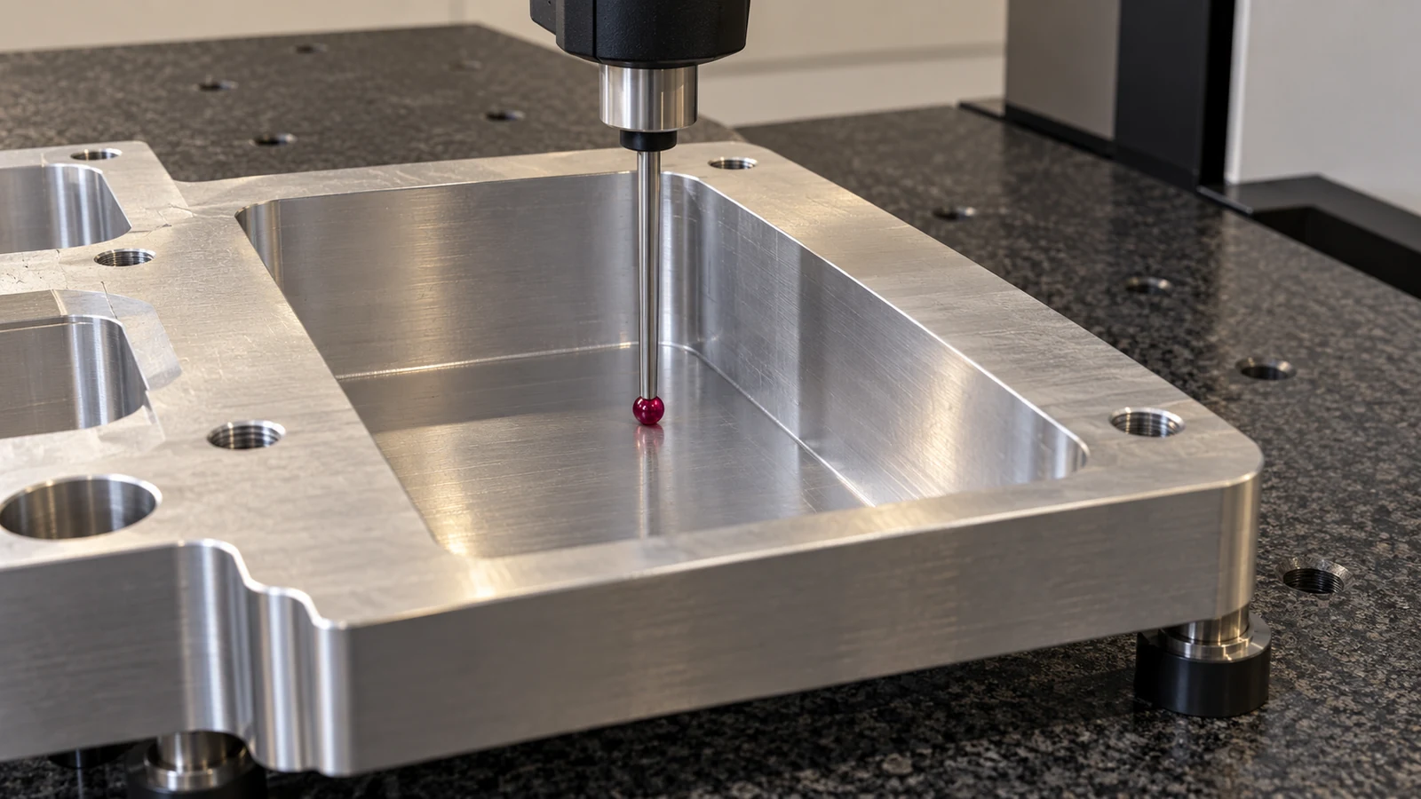
Check the feature that matters to the part: floor depth, wall position, corner radius, flatness, or the relationship between the pocket and its datum surfaces. Where the pocket is functional, define how it will be measured and whether a probe, CMM, height measurement, or another method can reach the relevant surfaces. Inspection access should influence the sequence before the part is clamped, not after the cavity is complete.
For thin or tall walls, monitor whether the roughing sequence releases material in a way that changes support. Alternating regions or leaving temporary webs may be appropriate for some geometries, but those decisions must be made from the drawing and setup—not assumed as a universal rule.
What to provide for a process review
A useful review needs more than pocket depth. Share the drawing or model, material and condition, stock size, pocket depth and opening, minimum wall thickness, required floor and wall tolerances, surface-finish callouts, datum scheme, and any restricted tool-entry areas. Note whether the feature is open or enclosed, which faces are accessible, and whether the part can be reoriented or must remain in one setup.
These details let a programmer compare axial roughing, side cutting, pre-drilling, and multi-axis access against the actual requirements. They also expose risks that a generic “deep pocket” label hides, such as a long unsupported wall, a critical seal surface, or a finish requirement at the bottom of a narrow cavity.
Frequently asked questions
Does plunge milling eliminate chatter?
No. It can reduce the lateral bending demand in a suitable setup, but chatter can still come from tool geometry, axial instability, holder condition, workholding, or poor chip evacuation.
Can a regular end mill be used for plunge milling?
Only if its geometry and manufacturer guidance support the intended plunging operation. Check center-cutting capability, chip clearance, and the recommended cutting conditions for the actual material.
Is plunge milling a finishing method?
Usually it is evaluated as a roughing strategy. A separate operation may be needed to bring pocket walls, floors, corners, and surface finish to drawing requirements.