
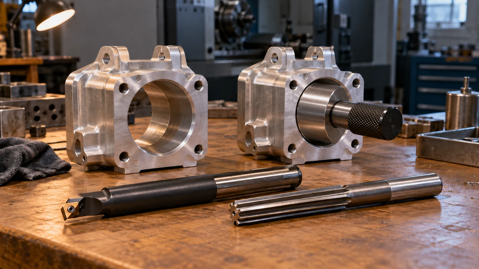
A pin can enter a machined hole and the assembly can still bind. A bearing may fit the measured diameter yet sit off-axis. Those failures expose a common mistake in a CNC drawing: treating hole size as if it also controls location, shape and alignment. Boring and reaming are both ways to finish an existing hole, but they solve different problems. Reaming is usually a sensible route when a prepared hole already has acceptable position and form and needs a controlled final diameter. Boring is worth considering when the hole axis, roundness, taper or relationship to a datum must be corrected as well as the size.
First identify the error the operation must fix
Before specifying a tool, separate four characteristics that are often compressed into the phrase “precision hole.” Diameter controls fit. Position locates the hole relative to the part’s datums. Form describes conditions such as roundness, cylindricity and taper. Surface condition affects sliding, sealing, wear or lubricant retention. A diameter reading alone cannot confirm the other three.
Consider a dowel hole in a two-piece fixture. If its diameter is correct but the center is displaced, the dowel can still jam during assembly. A reamer cuts material from the existing wall and generally follows the prepared hole; it should not be relied on to relocate an incorrectly positioned axis. A controlled boring operation may improve the location and geometry of that pre-hole, provided the setup references the correct datums and leaves sufficient material to remove. Neither process can rescue every misplaced hole: correction depends on stock allowance, access, tool rigidity and the allowable final geometry.
This is a narrower decision than the overall CNC hole machining process, which covers drilling, interpolation, blind holes and other hole features. Here the question is specifically which finishing route can address the feature that is failing in use.
Boring and reaming solve different problems
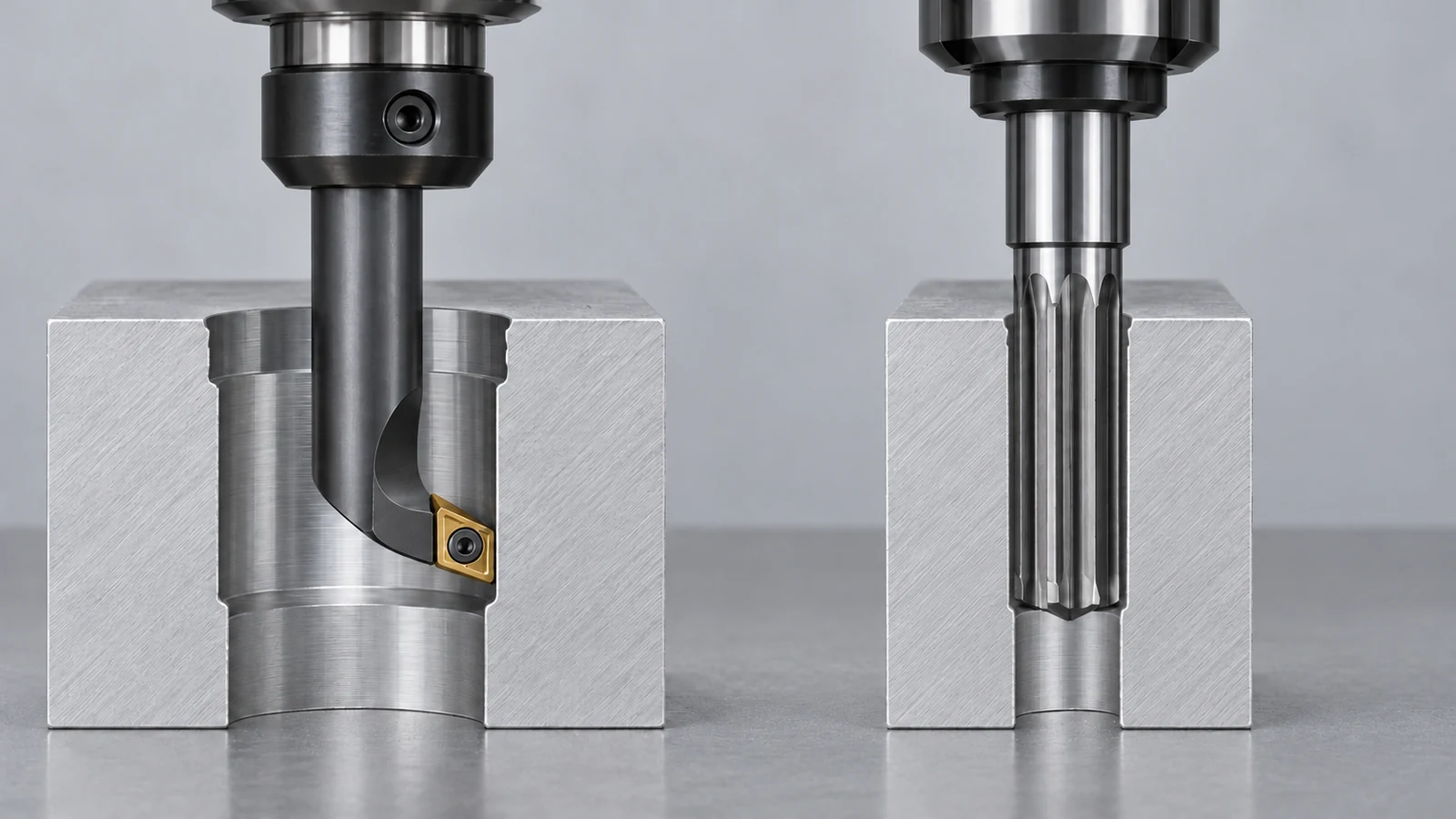
A boring tool removes material from an existing hole with a controlled cutting path. Depending on the machine and geometry, the tool may be adjustable to produce a particular finished diameter and can establish an axis from the setup rather than simply inherit the pilot hole’s path. A reamer is a multi-edge finishing tool that removes a small, planned allowance from a prepared hole. Its value is efficient, repeatable finishing when the pre-hole is already in the right place and sufficiently straight.
| Decision point | Boring | Reaming |
|---|---|---|
| Main purpose | Enlarge or refine a hole while controlling its axis and geometry from the setup. | Bring a prepared hole to a controlled final size and surface condition. |
| Pre-hole location | May correct some location error when stock and access permit. | Generally follows the pre-hole; not a dependable correction for misplaced holes. |
| Diameter flexibility | Can accommodate nonstandard sizes through tool adjustment or programming. | Usually needs a reamer suited to the required final size. |
| Stock condition | Needs enough uniform material for a stable finishing cut. | Needs a suitable, consistent finishing allowance; excessive stock or a poor pilot hole raises risk. |
| Production concern | Tool deflection, setup stability and measurement feedback. | Pre-hole quality, tool wear, chip control and size drift. |
The table describes process tendencies, not guaranteed factory capability or a universal tolerance ranking. Either method can fail when a thin wall deflects, a long tool vibrates, the workpiece moves in the fixture, or the inspection references a different datum from machining. Some parts need both operations: boring first to establish a suitable axis and geometry, followed by reaming only if that additional finish step serves a defined requirement. Adding both by habit increases cost without necessarily improving function.
Choose from the mating function, not a preferred tool
Locating dowel or guide pin
First establish the required fit and the position of the hole pattern to the assembly datums. If a drilled pilot already has acceptable location and straightness, reaming may efficiently deliver the final size. If the pilot is displaced or its form is inadequate, evaluate boring or another corrective route before the finish pass. A tight diameter tolerance by itself does not ensure two dowels will enter a mating component.
Bearing or bushing seat
For a bearing seat, the controlling questions may include the bore’s size, roundness, axial alignment with another seat, shoulder perpendicularity and surface requirement. Boring can be valuable when these relationships must be established in one controlled setup. Reaming may be suitable for certain prepared seats, but the choice should follow the bearing or bushing specification and the assembly method; do not assume every bearing bore needs the same sequence.
Clearance or non-locating hole
If a hole only clears a fastener, drilling or circular interpolation may already meet the function. Paying for a reamer or boring operation solely because the hole looks important on the model can add setup and inspection cost without changing assembly performance. Define which holes actually locate, seal or guide, then reserve finishing operations for those features.
In the wider CNC machining process, these choices belong after the drawing and datum review, not as an isolated tool-selection step.
A realistic process sequence for critical bores
A workable route starts with a stable reference, a suitable pilot hole and a measured finishing allowance. The precise order is part-specific, but the following checkpoints prevent a common error: discovering after finishing that the axis was never controlled.
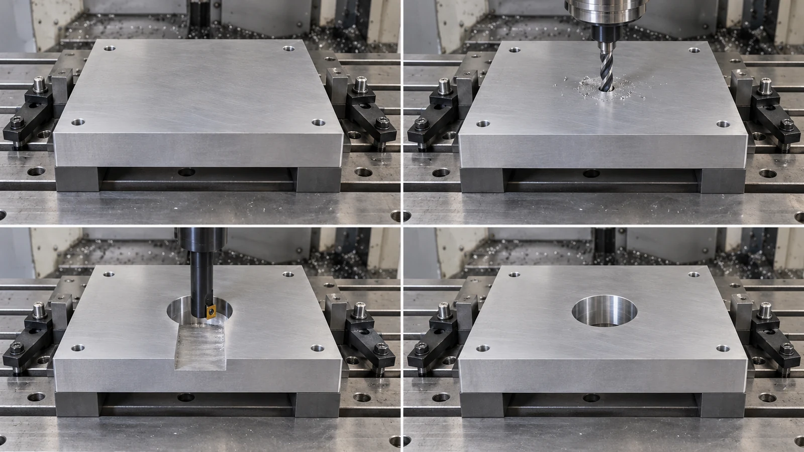
- Establish the datum strategy. Identify the surfaces and features used to locate the part for machining and inspection. If two bores must align, plan whether they should be finished in the same setup.
- Prepare the opening. Drill, interpolate or rough-bore the pilot with enough material for the next operation. Confirm access, chip removal and tool clearance in blind or stepped features.
- Measure the pilot where risk is high. Check whether its location, straightness and remaining stock allow the planned final operation. A reamer cannot be a substitute for this check when position matters.
- Finish for the controlled characteristic. Bore when the axis or form must be established or corrected; ream when the pre-hole is already sound and the final size and surface are the remaining work. Combine methods only for a justified reason.
- Deburr, clean and inspect. An entry burr can alter a pin-gauge reading; a chip left in a blind bore can interfere with the mating part. Final inspection should use the drawing’s datum system.
For a thin-wall housing, fixture pressure and material removal can change the bore after the part is released. For a deep bore, tool reach and chip evacuation may dominate the route. Those conditions can overturn a seemingly simple “boring versus reaming” rule.
How to verify the result without missing the failure
Match the measurement to the acceptance criterion. A plug or pin gauge can check a functional size limit, but it will not by itself report where the hole is relative to datums. A bore gauge or suitable internal measurement can compare diameter at more than one depth and angular orientation, helping reveal taper or out-of-round behavior. Coordinate inspection can evaluate the hole axis and pattern against the drawing’s datum reference frame when the setup and measurement strategy are appropriate.
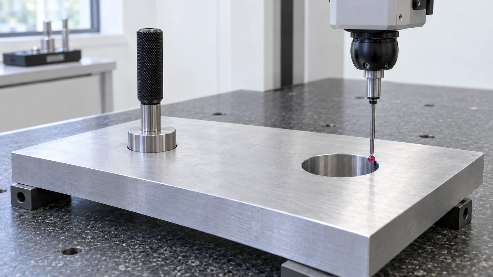
A useful inspection plan answers three questions: Which characteristic is controlled? At what condition is it measured—while clamped, after release, or after coating? What evidence will the buyer receive? If a part passes a size gauge yet fails assembly, check position, perpendicularity and the mating component before tightening the diameter tolerance.
The distinction between size and geometric location is developed further in the site’s GD&T drawing guide. When a project needs a documented inspection approach, the quality-control page explains the site’s stated inspection framework; specific methods and deliverables should still be agreed against the drawing.
What changes between a prototype and a production run
A prototype can demonstrate that one bore fits. Production must maintain that fit and the required location across repeated setups, stock variation and tool wear. Reaming often offers an efficient repeated finish when the preceding operation remains stable, but gradual tool wear or an inconsistent pilot can shift results. Boring permits adjustment and feedback for certain sizes and geometries, yet it also depends on repeatable fixturing and tool condition.
Before scaling, decide which feature will be checked at first article, which measurements will be sampled during the run, and which signals trigger a tool change or offset review. Record whether the acceptance requirement is a size range, a geometric tolerance, a surface specification or a combined functional fit. A process capability claim without the material, geometry, measurement method and sampling conditions is not a useful purchasing guarantee.
What the drawing and RFQ should communicate
Specify the result the mating part needs; allow the manufacturer to choose a practical process unless the operation itself is a controlled requirement. A useful package identifies the hole’s function, nominal diameter and fit, depth and bottom condition, datum references, position or orientation controls where needed, material and condition, edge treatment, surface requirement, and inspection evidence. For a pattern of locating holes, include the mating geometry or explain the assembly relationship rather than only tightening every diameter.
When requesting a quote, include the current CAD model and drawing revision, quantity, prototype or production status, and any coating that may affect the final bore. State whether the supplier should measure the feature before or after finishing treatment. If the drawing says “ream all holes” but only one hole locates the assembly, clarify that distinction before pricing. The result may be a simpler route for clearance holes and a more controlled route for the critical feature.
Frequently asked questions
Can reaming correct a hole that was drilled off location?
Do not count on it. A reamer normally follows the prepared hole. If location is outside the allowed datum-based tolerance, assess whether enough material remains for boring or another corrective operation. Severe error may require remaking the part.
Is a bored hole always more accurate than a reamed hole?
No. Accuracy depends on which characteristic is being judged, the pre-hole, machine and fixture rigidity, tool condition, material, depth and measurement method. Boring offers more control over the axis in suitable setups; reaming can efficiently control the final size of a well-prepared hole.
Should a drawing specify boring or reaming?
Usually specify the functional result—fit, geometry, datums and finish—and let the supplier select a route. Name the process when it is genuinely required by an approved design, validation plan or downstream assembly constraint.
Can a pin gauge prove the hole pattern is correct?
A pin gauge can help verify size or a particular functional fit. It does not automatically prove the pattern’s position relative to datums. Use an inspection method that evaluates the actual geometric requirement.