
This guide separates locating from clamping, accuracy from repeatability, and tool mass from stiffness. It provides a design and RFQ framework for nests, pallets, gauges, grippers, EOAT plates, sensor brackets, and automated assembly fixtures.
Draw the Locating Chain
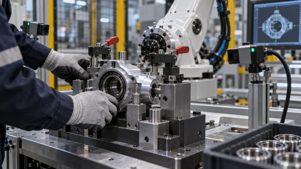 Trace coordinates from the machine or cell base through robot flange, tool plate, gripper, locators, workpiece, process feature, and inspection reference. Mark every joint, adapter, dowel, fastener, calibration transform, and compliant element. The chain reveals where error and deflection accumulate.
Decide whether the fixture establishes product datums or merely supports handling. A camera, probe, or force-control step may compensate for some variation, but it should not mask unstable mechanics. Mechanical repeatability and calibration strategy must be planned together.
Trace coordinates from the machine or cell base through robot flange, tool plate, gripper, locators, workpiece, process feature, and inspection reference. Mark every joint, adapter, dowel, fastener, calibration transform, and compliant element. The chain reveals where error and deflection accumulate.
Decide whether the fixture establishes product datums or merely supports handling. A camera, probe, or force-control step may compensate for some variation, but it should not mask unstable mechanics. Mechanical repeatability and calibration strategy must be planned together.
Constrain the Part Without Fighting It
 Use a deterministic locating scheme appropriate to the geometry. The familiar principle of constraining degrees of freedom is more important than the number of locator pins. Redundant contacts can rock on variable parts, while insufficient support allows movement under process load.
Locate on stable functional surfaces and allow chips, flash, coating, burrs, or molded variation to escape. Reliefs, replaceable buttons, nests, cones, V-blocks, and compliant elements can accommodate the real incoming part. A perfect CAD contact over a large area may be less repeatable than a small controlled contact set.
Make incorrect loading difficult. Asymmetric locators, presence sensors, keyed interfaces, and clear orientation features reduce automation faults before software must detect them.
Use a deterministic locating scheme appropriate to the geometry. The familiar principle of constraining degrees of freedom is more important than the number of locator pins. Redundant contacts can rock on variable parts, while insufficient support allows movement under process load.
Locate on stable functional surfaces and allow chips, flash, coating, burrs, or molded variation to escape. Reliefs, replaceable buttons, nests, cones, V-blocks, and compliant elements can accommodate the real incoming part. A perfect CAD contact over a large area may be less repeatable than a small controlled contact set.
Make incorrect loading difficult. Asymmetric locators, presence sensors, keyed interfaces, and clear orientation features reduce automation faults before software must detect them.
Clamping Should Hold, Not Relocate
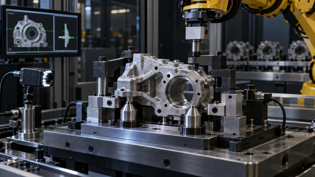 Apply clamp force toward the locators and supports. Sideways or unbalanced force can slide the workpiece away from its intended datum. Thin, soft, or cosmetic parts may need distributed, limited, or compliant clamping.
EOAT Lives in a Moving Coordinate System
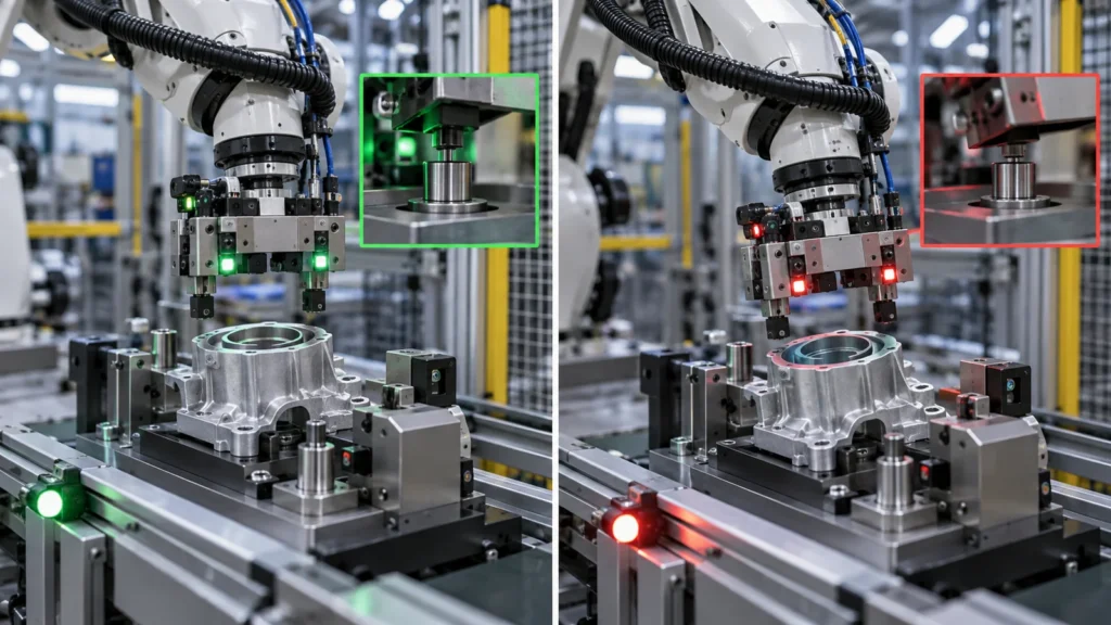 End-of-arm tooling affects robot payload, center of gravity, inertia, acceleration, reach, collision envelope, and settling time. A thick solid plate may be easy to machine but reduce cell performance. Aggressive pocketing saves mass but can reduce stiffness or create vibration.
Place mass close to the flange, follow the load path, and evaluate worst-case part weight and orientation. Check deflection under gripping, acceleration, process contact, and emergency stop. Modular interfaces can speed changeover but add joints and stack-up.
Material selection balances stiffness-to-mass, wear, crash behavior, corrosion, conductivity, and repair. Aluminum plates with steel or hardened replaceable contacts are common in principle, but the actual design follows duty.
End-of-arm tooling affects robot payload, center of gravity, inertia, acceleration, reach, collision envelope, and settling time. A thick solid plate may be easy to machine but reduce cell performance. Aggressive pocketing saves mass but can reduce stiffness or create vibration.
Place mass close to the flange, follow the load path, and evaluate worst-case part weight and orientation. Check deflection under gripping, acceleration, process contact, and emergency stop. Modular interfaces can speed changeover but add joints and stack-up.
Material selection balances stiffness-to-mass, wear, crash behavior, corrosion, conductivity, and repair. Aluminum plates with steel or hardened replaceable contacts are common in principle, but the actual design follows duty.
Sensors, Cables, and Pneumatics Belong in the Mechanical Design
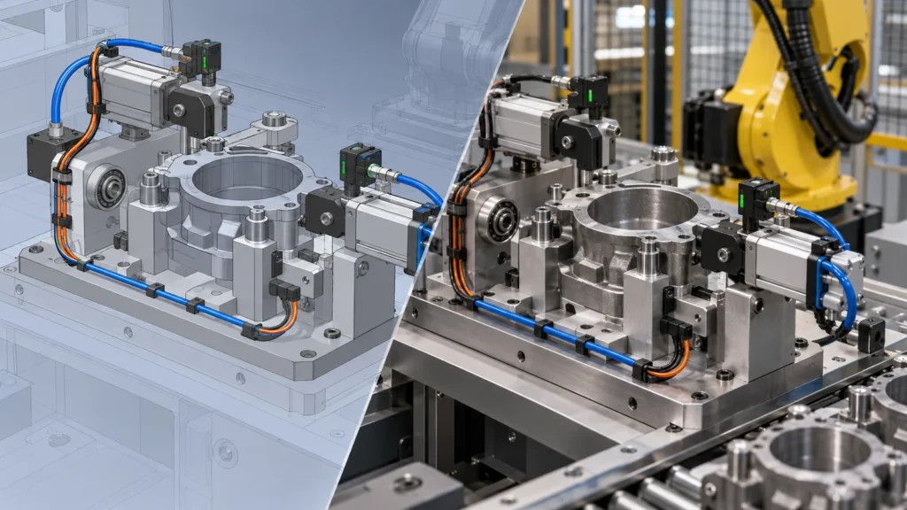 Presence sensors, pressure switches, proximity targets, cameras, and force devices need protected mounting, adjustment, and calibration access. Their brackets should reference the same functional chain as the feature they detect.
Route cables and hoses through the full motion envelope. Control bend radius, torsion, strain relief, abrasion, connector access, and snag risk. A fixture that works on a bench can fail after repeated robot movement if dress components pull on the tool or obscure sensors.
Design service access. Consumables and connectors should be replaceable without dismantling the datum structure or requiring complete recalibration.
Presence sensors, pressure switches, proximity targets, cameras, and force devices need protected mounting, adjustment, and calibration access. Their brackets should reference the same functional chain as the feature they detect.
Route cables and hoses through the full motion envelope. Control bend radius, torsion, strain relief, abrasion, connector access, and snag risk. A fixture that works on a bench can fail after repeated robot movement if dress components pull on the tool or obscure sensors.
Design service access. Consumables and connectors should be replaceable without dismantling the datum structure or requiring complete recalibration.
Design Wear Into Replaceable Elements
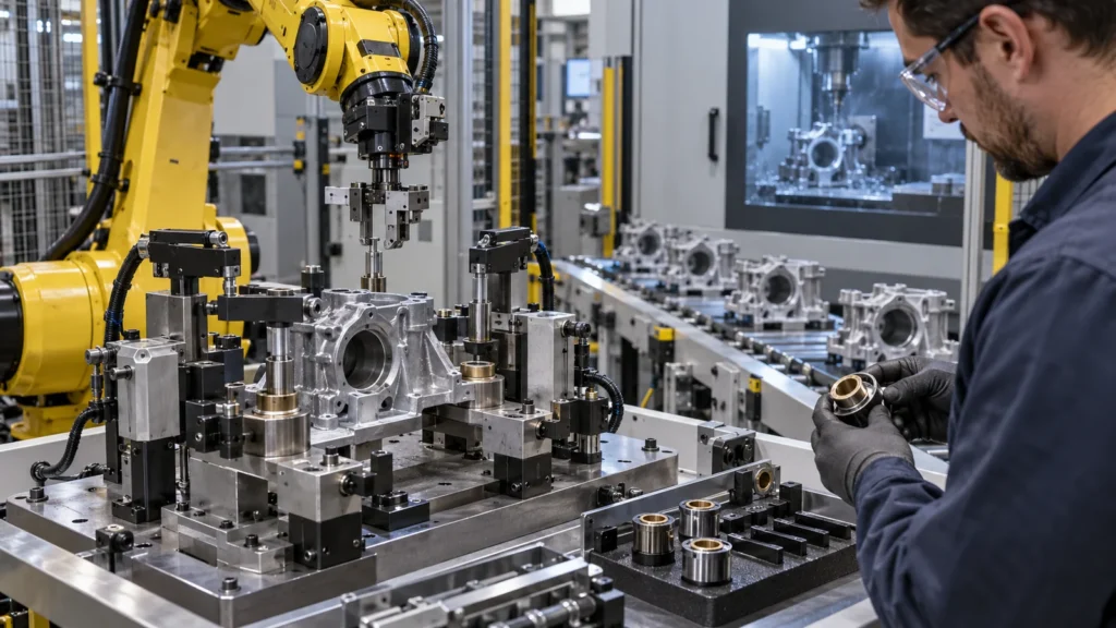 Locators, bushings, pads, gripper fingers, seals, and hard stops wear or become damaged. Put wear into removable components with controlled fits and accessible fasteners. Record replacement intervals or condition limits based on cycles and observed drift.
Protect fixture datums during cleaning and maintenance. If a replacement pin can be installed in multiple positions or a pad thickness changes without detection, maintenance can shift the system. Use keyed parts, gauges, or verification routines after service.
The Controle de qualidade CNC approach should include fixture status because tooling variation becomes product variation.
Locators, bushings, pads, gripper fingers, seals, and hard stops wear or become damaged. Put wear into removable components with controlled fits and accessible fasteners. Record replacement intervals or condition limits based on cycles and observed drift.
Protect fixture datums during cleaning and maintenance. If a replacement pin can be installed in multiple positions or a pad thickness changes without detection, maintenance can shift the system. Use keyed parts, gauges, or verification routines after service.
The Controle de qualidade CNC approach should include fixture status because tooling variation becomes product variation.
Verify the Cell, Not Only the Machined Tool
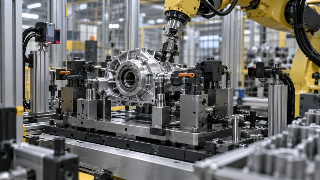 A dimensional report proves the tool matches its drawing. Cell acceptance should also test loading, repeatability, misload detection, cycle time, sensor function, clamp confirmation, collision clearance, part variation, maintenance access, and recovery after fault.
Use a representative range of parts rather than one ideal sample. Measure output under normal robot speed and process load. If calibration is required, define master artifacts, frequency, responsibility, and change control.
Functional gauges and capability studies may reveal system behavior that isolated CMM data cannot. Keep mechanical and software revisions linked so a changed locator does not leave an old robot frame in service.
A dimensional report proves the tool matches its drawing. Cell acceptance should also test loading, repeatability, misload detection, cycle time, sensor function, clamp confirmation, collision clearance, part variation, maintenance access, and recovery after fault.
Use a representative range of parts rather than one ideal sample. Measure output under normal robot speed and process load. If calibration is required, define master artifacts, frequency, responsibility, and change control.
Functional gauges and capability studies may reveal system behavior that isolated CMM data cannot. Keep mechanical and software revisions linked so a changed locator does not leave an old robot frame in service.
Automation-Tooling RFQ Package
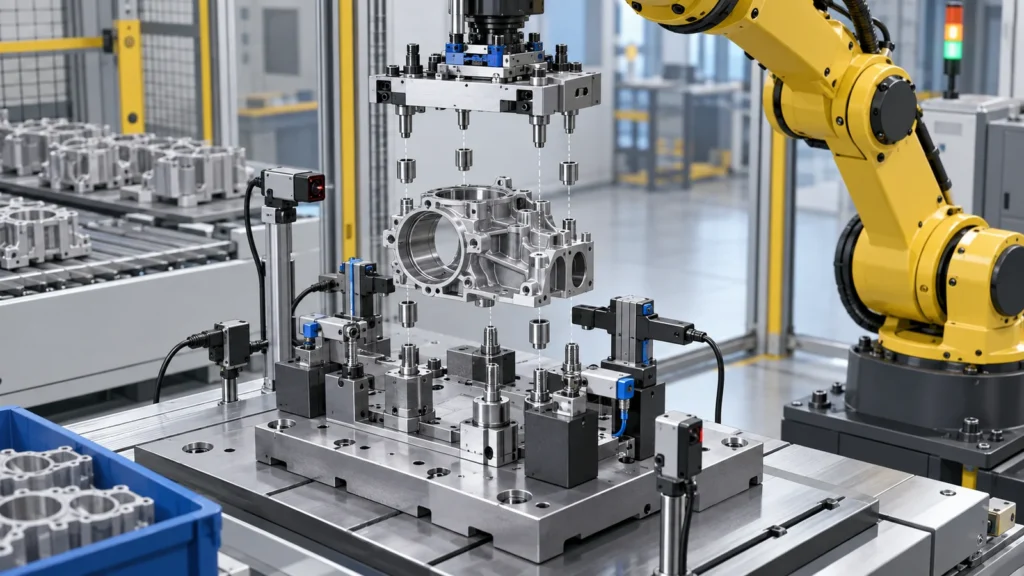
This system view extends the parent aplicações da usinagem CNC article into automation tooling.
Fixture and EOAT FAQs
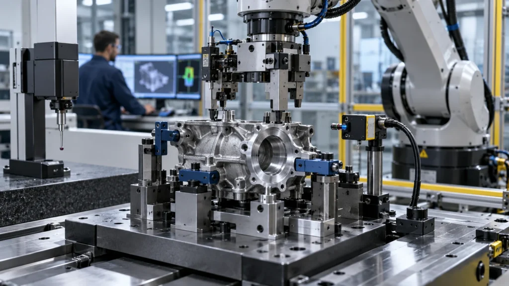
No. Tolerances should support the locating chain and replaceability. Overly tight nonfunctional dimensions add cost without improving cell repeatability.
Can robot calibration correct a flexible tool?
Calibration can correct repeatable geometric offset, not variable deflection, wear, loose joints, or changing load. Mechanical stability remains necessary.
When should hardened inserts be used?
Use them where wear, impact, sliding, or frequent replacement justifies a harder contact. Their fit, retention, replacement method, and effect on the datum must be designed.