
A broad, accessible datum face and a pocket floor may both look flat in CAD, but they do not present the same cutting problem. Face milling is usually considered for open planar areas; end milling is used when the tool must enter or follow bounded geometry such as pockets, slots, shoulders, and profiles. The decision depends on access, feature boundaries, wall rigidity, surface requirements, and the setup—not on which cutter sounds more powerful. The CNC milling process guide places the choice within the complete milling route.
Read the feature boundary before choosing a cutter
Face milling removes material across an exposed plane, with the cutter axis generally normal to that face. End milling uses the end and peripheral cutting edges of an end mill, so the tool can create a face while also following walls, pockets, slots, and contours. The categories overlap in practice: an end mill can face a small area, and a face mill may clean a broad plane. The useful question is which toolpath can reach the required surface while controlling the part’s functional geometry.
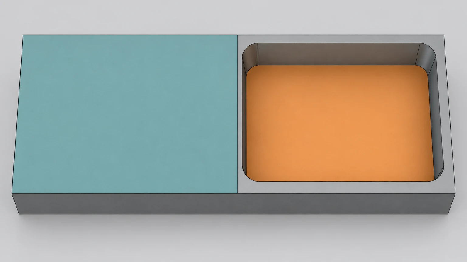
Start by marking the surface’s role. Is it a datum used to locate later features? Is it a cosmetic outer face, a sealing land, a mating plane, or simply stock cleanup? Then identify boundaries: open edges, steps, ribs, clamps, holes, and nearby walls. A wide open plane can favor a face-milling approach; a floor bounded by vertical walls may require an end mill and a path that respects corner radius and tool reach.
What each milling route is suited to
This comparison is about part geometry and the result to control. It is not a universal ranking of cycle time or surface finish; those depend on the cutter, machine, material, engagement, setup, and inspection plan.
| Condição da peça | Face-milling route | End-milling route |
|---|---|---|
| Wide, open plane | Often a natural option when access and machine envelope allow it | Useful for localized areas or when another feature uses the same setup |
| Pocket floor or enclosed step | May be blocked by surrounding walls or toolholder clearance | Can enter the bounded feature; reach and corner radius must be checked |
| Thin or flexible section | Broad engagement can still deflect an inadequately supported part | Side forces and tool reach can affect walls and narrow lands |
| Datum face | Plan the stock allowance, flatness target, and datum sequence | Can finish local datum features, but step relationships require explicit control |
| Internal corner | Does not remove the corner radius left by a rotating tool in a pocket | Leaves a radius tied to tool geometry unless a secondary route is planned |
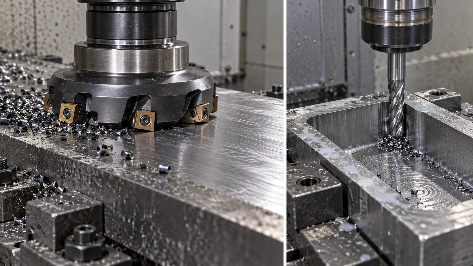
The table is a starting point, not a process guarantee. Interrupted surfaces, clamping positions, cutter diameter, spindle orientation, and remaining stock can change the preferred route. A part with several connected faces may use both methods in sequence.
Use a geometry-first decision sequence
- Identify the functional surface. Separate a datum or sealing face from a noncritical stock-removal surface so the drawing does not apply the same finish or tolerance everywhere.
- Check access and boundaries. Confirm the cutter and holder can reach the plane without colliding with walls, clamps, bosses, or an adjacent feature.
- Assess stiffness. Review unsupported wall height, material left after machining, and the workholding direction. A flexible part may require a different sequence or support plan.
- Define the corner condition. A pocket milled with a round cutter naturally retains an internal radius. State the acceptable radius or relief rather than implying a sharp internal corner.
- Choose the inspection reference. If the plane locates other features, specify its datum relationship and the measurement condition before selecting a finishing route.
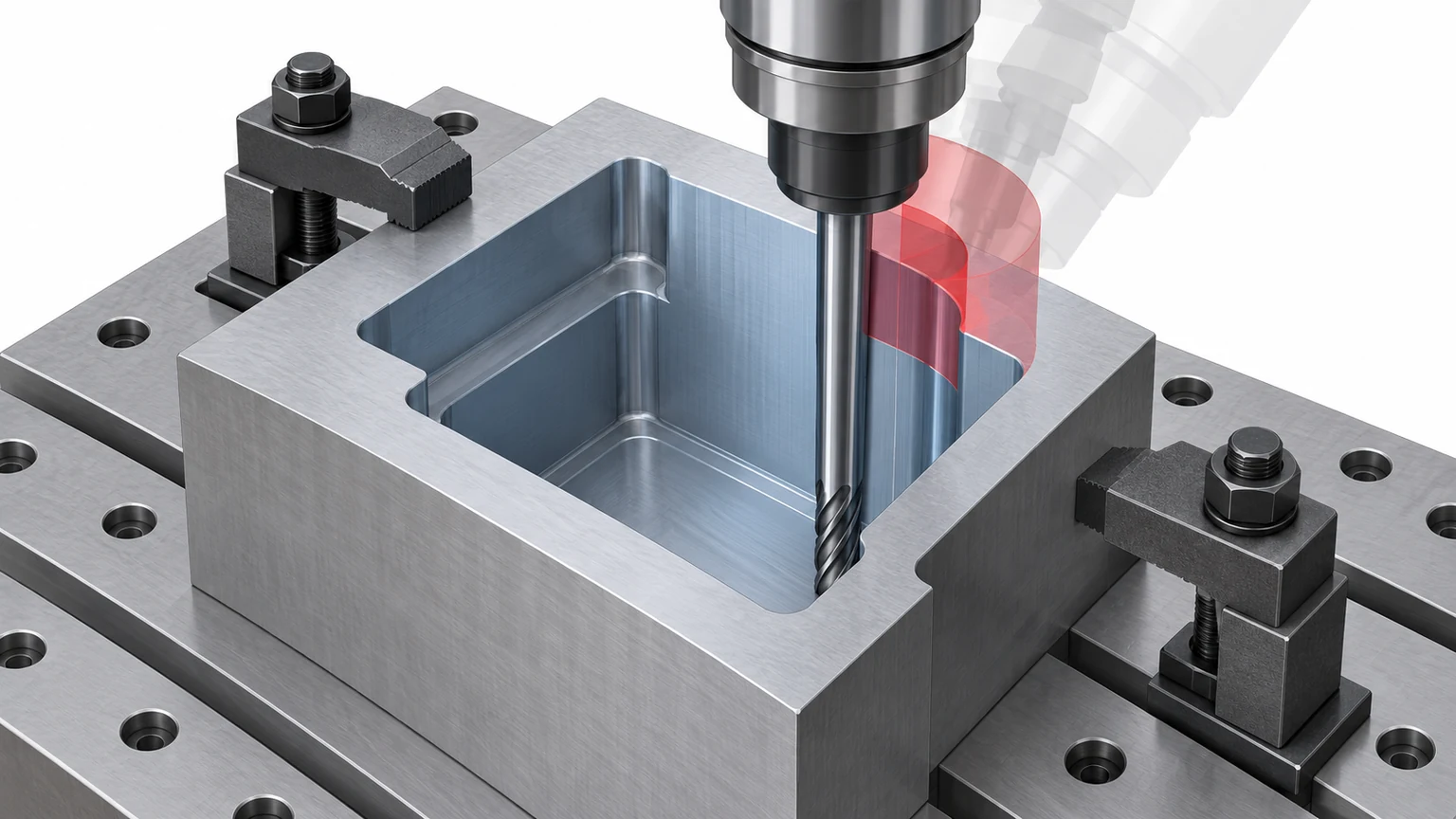
This sequence avoids a common design trap: naming a cutter operation before deciding what the surface must do. If the component has a narrow, flexible wall, also consider the restraint and release effects covered in the thin-wall milling workholding guide.
Protect the datum and the finish requirement
A visually smooth face is not necessarily flat enough to locate an assembly, and a flat surface does not automatically satisfy a specified roughness or parallelism requirement. Keep size, form, orientation, and texture requirements separate on the drawing. The inspection method should match the feature and datum scheme, especially when one face controls a hole pattern or a mating component.
When a face is a datum, the machining sequence matters: establish the reference surface, maintain it through later setups, and avoid measuring a feature from a different temporary contact plane. For a cosmetic face, the requirement may instead focus on visible tool marks, edge breaks, or consistent appearance. Do not use a blanket “fine finish” note when only one region is functional.
What to show on the drawing or RFQ
For a useful manufacturing review, provide the 3D model and controlled drawing, material and stock condition, production quantity, critical datum faces, surface-finish requirements, and any restricted tool-access zones. Identify which planar regions must be coplanar or parallel, and call out internal corner limits where mating parts depend on clearance.
If the design permits either face milling or end milling, specify the required part result rather than forcing a particular cutter. If the process itself matters—for example, because of a finish pattern, thin-wall response, or an inspection plan—explain that requirement in the drawing notes or RFQ so the supplier can assess it before quoting.
Face and end milling FAQs
Can an end mill machine a flat face?
Yes. It can machine a plane, particularly a localized or bounded area. Tool reach, engagement, support, and the required surface result determine whether it is suitable.
Is face milling always faster on a large surface?
No. Cutter size, machine capability, material, stock allowance, fixture access, and setup can change the comparison. The drawing geometry should be reviewed before cycle-time assumptions are made.
Do these methods create sharp internal corners?
No. A rotating cutter leaves a radius at an internal corner. Specify a permissible radius or discuss a different feature design if the mating geometry needs more clearance.