
Vapor polishing can improve the clarity and apparent smoothness of compatible CNC plastics by briefly softening and reflowing the outer surface. It does not correct toolpath errors, deep scratches, internal stress, poor material choice, or geometry that prevents controlled exposure. The best results come from designing the machining, stress management, edge condition, polishing route, and optical inspection as one process—not from treating vapor polishing as a universal rescue step.
Why a Clear Plastic Turns Hazy After Machining
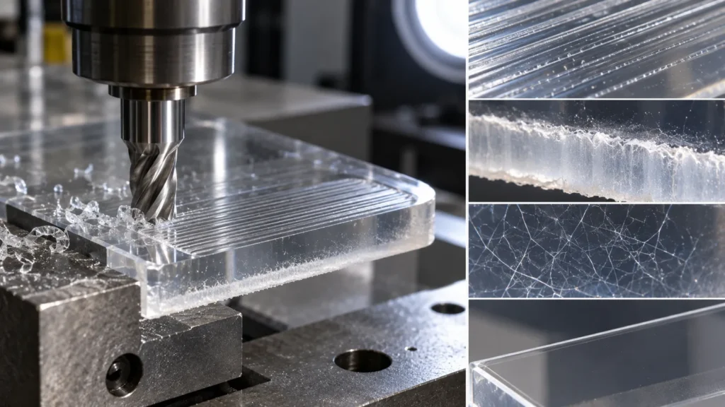
Machining marks
Feed lines and tool geometry create a regular frosted appearance.
Heat and stress
Local softening, cracking, or locked-in stress can appear during or after finishing.
Material behavior
Different polymers respond differently to cutters, coolants, solvents, and polishing routes.
If the part is already cracked, crazed, dimensionally unstable, or made from an incompatible polymer, vapor polishing may amplify the problem rather than hide it. Review material choice through the guia de materiais para usinagem CNC before committing the finish.
What Vapor Polishing Actually Changes
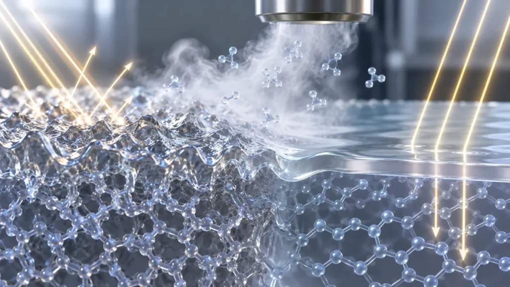
The same mechanism creates risk. Too much exposure can round edges, soften details, distort thin features, close small openings, alter gloss unevenly, or reveal stress through crazing. Geometry, material batch, prior machining, cleaning, temperature, fixturing, exposure, and drying all influence the result.
Surface reflow can also change how a defect appears without removing its root cause. A chatter valley may become glossy yet remain optically distorted. A stressed corner may look acceptable at inspection and craze later when exposed to cleaning chemicals or assembly load. The process review therefore needs both immediate appearance and delayed service behavior.
For channels and enclosed cavities, access is only half of the problem. The process must also support predictable evacuation, drying, and cleanliness. A clear exterior is not acceptable if hidden passages retain residue or if the treatment changes fluid-contact requirements.
Compatibility Comes Before Clarity
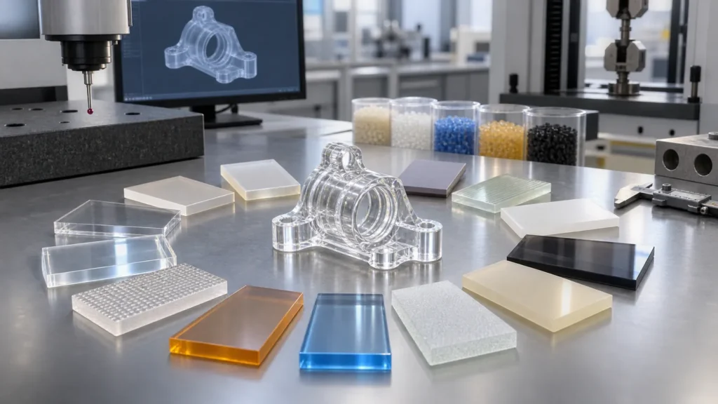
| Input to confirm | Por que isso importa | Evidence to provide |
|---|---|---|
| Exact resin and grade | Chemical response and stress cracking vary by formulation | Material designation and supplier data |
| Color and additives | Pigments, fillers, and reinforcement can change appearance | Production-intent stock or representative coupon |
| Prior heat and stress history | Residual stress can become visible during chemical exposure | Machining route, stock form, and any annealing requirement |
| Service contact | Optical, medical, fluid, vacuum, or chemical use may restrict residues and methods | Application, cleaning, regulatory, and compatibility requirements |
Traceability becomes important when clarity is part of product performance. Keep production stock consistent with the approved trial, and record any resin-source or grade change before processing. Two plastics sold under a similar family name may not behave identically because formulation and stress history differ.
When the part will contact alcohols, cleaners, fuels, adhesives, or sterilization media, include that exposure in validation. A surface that survives polishing may still be incompatible with the chemicals encountered later in service.
The Geometry Risk Map
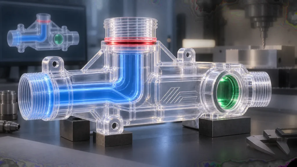
- Red—protect or exclude: sealing lands, precision bores, threads, sharp optical edges, calibrated flow openings, engraved scales, and adhesive-bond areas.
- Amber—validate by sample: thin walls, ribs, deep recesses, intersections, snap features, and regions with heavy stock removal.
- Green—primary polish zones: accessible viewing windows and broad surfaces with enough dimensional freedom.
The map also supports fixturing and inspection. A housing may need clarity only through one window, while the flange, ports, and mounting bosses must preserve their machined condition. Selective requirements are easier to control than “polish entire part.”
Vapor, Flame, or Mechanical Polishing?
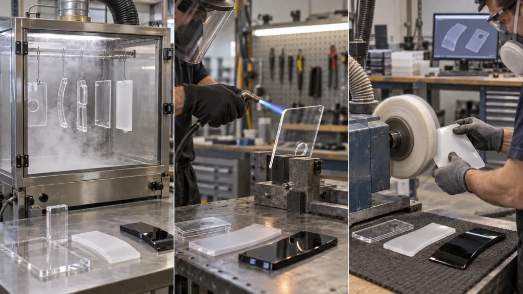
A hybrid route may use fine machining followed by controlled polishing. The site’s CNC post-processing overview helps frame this as part of the full manufacturing route rather than a stand-alone cosmetic operation.
Clarity Begins at the Cutting Tool
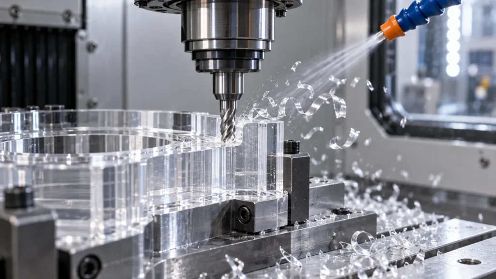
A useful process sequence
- Verify material identity and condition before machining.
- Rough the part while controlling heat and residual stress.
- Allow an appropriate stabilization step where the material and geometry require it.
- Finish critical geometry with sharp tooling and a stable path.
- Remove burrs without damaging optical zones.
- Clean using a method compatible with the polymer and polish route.
- Run a representative polishing trial before locking production settings.
Define “Clear” So It Can Be Inspected
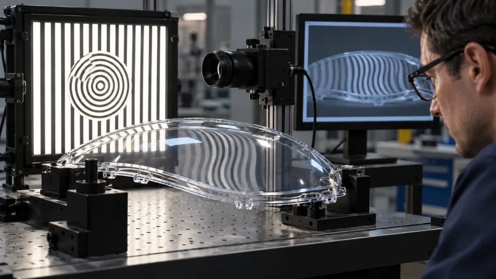
| Acceptance category | Possible control |
|---|---|
| Functional visibility | Readability or target recognition through the production geometry |
| Visual defects | Scratch, haze, bubble, streak, burn, inclusion, and edge limits by zone |
| Dimensions | Post-polish measurement of interfaces and wall geometry |
| Surface and cleanliness | Agreed roughness, residue, rinse, drying, and packaging criteria |
For critical projects, approve a polished first article and record the inspection conditions. JUCHENG’s quality control overview provides the context for dimensional and visual verification.
Do not judge a curved window with the same method as a flat coupon. Curvature, wall thickness, viewing angle, and internal reflections can make a conforming surface look distorted. Whenever possible, inspect through the production geometry using the real target or a representative optical setup.
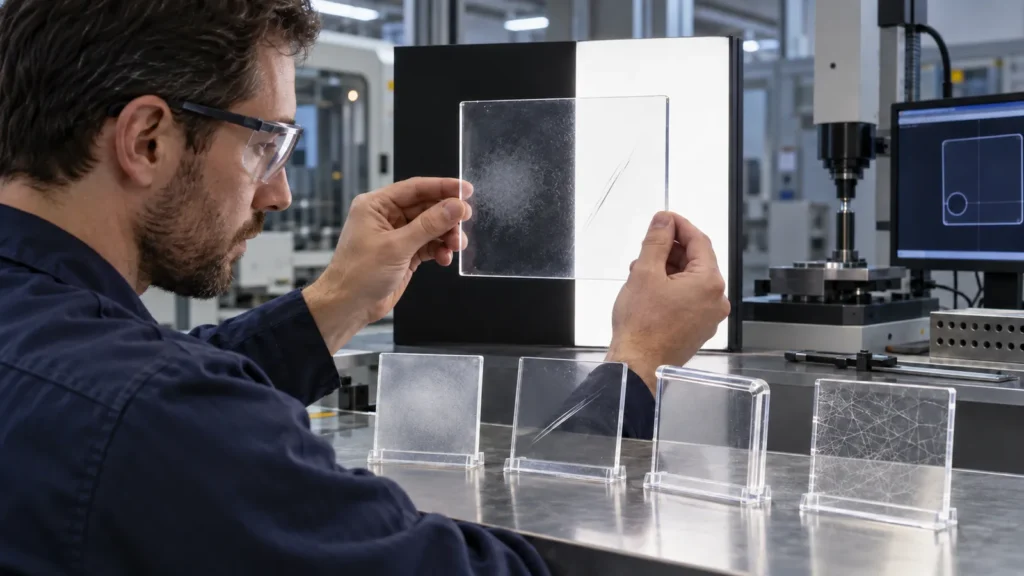
Photography can document gross defects, but camera exposure and lighting can hide haze or exaggerate scratches. Physical reference parts remain valuable for cross-border purchasing because they reduce ambiguity between words such as clear, transparent, glossy, and optical.
The RFQ Package for a Clear CNC Plastic Part
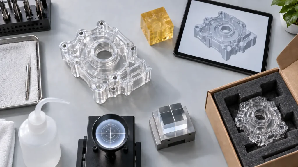
This package allows the supplier to judge whether vapor polishing is suitable, whether a machining-first improvement is enough, or whether another material or manufacturing route would lower risk.
Questions That Prevent Expensive Rework
No. Suitability depends on the exact polymer grade, additives, stress condition, geometry, application, and available controlled process. Confirm compatibility using production-intent material.
Will vapor polishing remove deep scratches?
It is intended to reflow the near surface, not erase deep damage without dimensional consequence. Deep scratches should be prevented or reduced before polishing, and critical wall thickness or geometry must still be protected.
Can a polished part still crack later?
Yes. Residual machining stress, incompatible chemicals, assembly load, sharp corners, temperature, and service exposure can contribute to delayed crazing or cracking. Surface clarity does not prove long-term stress resistance.