
UHMW guide rail expansion must be accommodated while the mounting scheme holds the guiding path in position. If both ends are rigidly trapped, growth can bow the rail, load fasteners or create a step at a joint. If every mounting point is loose, the rail can drift from its intended path. A practical design establishes one deliberate reference location, lets other points move along the rail, and checks that gaps and supports remain adequate over the expected temperature range. Use the coefficient and service limits for the specified grade, not a generic plastic value.
Estimate movement before laying out fasteners
For a first-order estimate of free thermal growth, use ΔL = α × L × ΔT, where α is the supplier’s linear expansion coefficient for the selected grade and direction, L is effective rail length, and ΔT is the temperature change from installation reference to operating condition. This is a planning estimate, not a mounting tolerance. Confirm the data source and temperature range, and consider whether the rail is constrained or exposed to gradients.
Define both installation and operating temperatures. A rail installed in a cool workshop and operated near a warm process may move differently from one installed at its normal service temperature. Cleaning cycles, sunlight, hot product contact and local heat sources can create uneven conditions. If those effects matter, evaluate sections and joints rather than applying one average temperature to the entire conveyor.
El sitio UHMWPE machining page addresses material-related machining scope. Grade selection and operating suitability still require the application conditions and supplier data.
Choose one reference point and guided movement
Pick a fixed point that establishes the rail’s position relative to the machine or product path. Other mounting points can use slots oriented along the rail so material can expand and contract while staying laterally supported. Slot travel should cover calculated movement plus installation and manufacturing allowances determined by the designer. A round hole at every station can unintentionally lock the rail at multiple points. To manage UHMW guide rail expansion, calculate slot travel from the selected grade’s coefficient, rail length and specified temperature range, then verify retention at both travel limits.
Do not widen holes without checking washer or retainer overlap, edge distance, support beneath the rail and fastener engagement. A slot that permits motion must also keep the guide from lifting, twisting or shifting across the conveyor. The support profile, rail cross-section, fastener head and clamp design work together; a component that pinches both sides of the slot can eliminate movement.
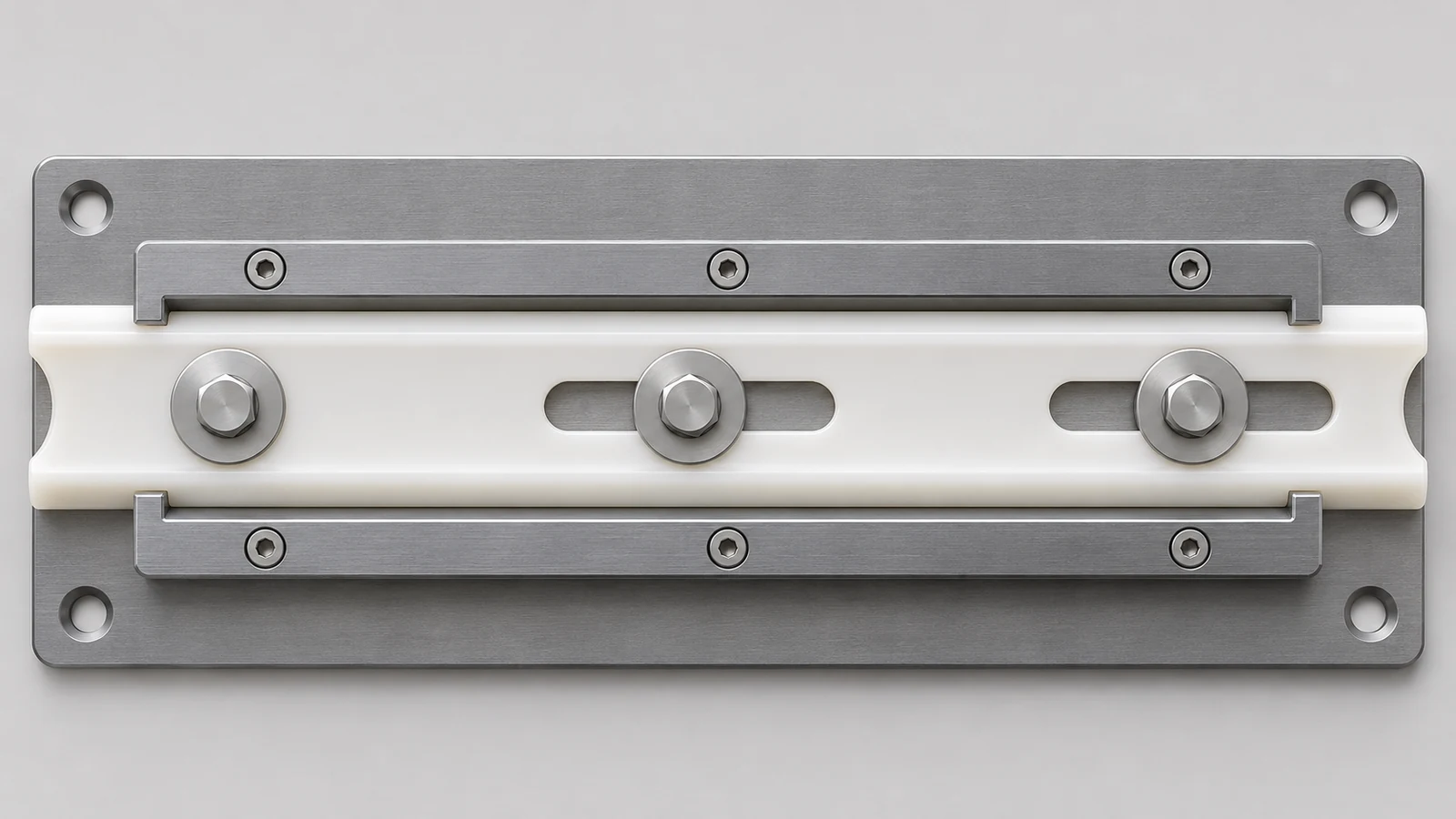
Design joints for growth without a catch point
Segmenting a long rail can limit movement accumulated at one end, but each joint introduces a possible gap, step or misalignment. Determine the joint gap at installation reference from expected movement and the fixed-point arrangement. Keep adjoining ends aligned in height and laterally, and orient or chamfer the transition where it could catch a conveyed product or chain.
Staggered joints may help avoid a continuous interruption across parallel guide runs, if the machine geometry and support allow it. Do not let thermal gaps expose a snag point, trap debris or interfere with product containment. Where the path is critical, define how the joint is measured at installation and how it should behave at the hottest or coldest expected condition.
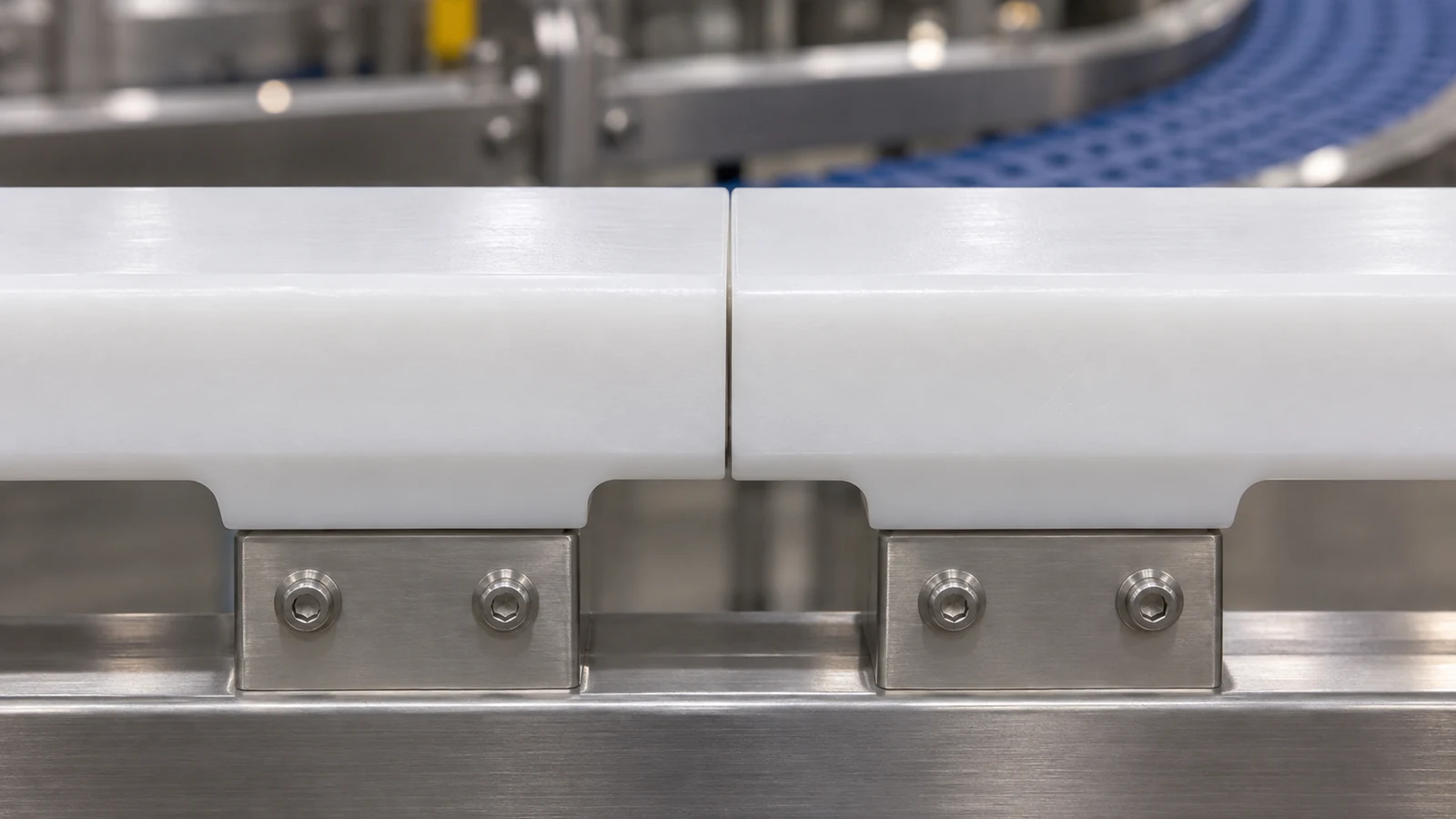
Keep clamping from defeating the slots
Fasteners should retain the rail without creating uncontrolled friction that prevents its intended slide. The designer must define whether the rail is clamped, captured, supported under a washer or held by a profile. A slotted hole alone does not guarantee movement if a fastener head locks the rail or a bracket squeezes it laterally.
Review movement in the cross-section as well as along the rail. An asymmetric profile may need lateral restraint while leaving longitudinal freedom. Check that support remains continuous where slots remove material, and that countersinks or fastener heads do not protrude into a moving chain or product path. Do not assume a steel-rail attachment can be copied unchanged for a polymer guide.
El materiales plásticos page gives broader CNC material context; it does not replace the selected grade’s data sheet.
Check the installed path across conditions
Inspect the rail after installation from the machine’s functional reference. Check path location as specified, joint steps and gaps, fastener engagement, support contact and clearance to the moving product or chain. Repeat the check at a representative operating condition when thermal movement is critical. Record temperature and the reference point so measurements are comparable.
If the rail bows, determine whether both ends or intermediate fasteners restrain it. If a joint opens unevenly, check the fixed point, segment lengths and installation temperature. If the guide drifts, inspect lateral capture, slot orientation, clamp friction and support. These symptoms have different causes; changing the gap alone may not solve the mounting problem.
Specify a rail that can be mounted and inspected
A useful drawing or assembly note identifies grade, rail length and segments, installation temperature reference, fixed point, slot direction and travel, fastener and washer arrangement, joint gap, support profile and inspection reference. State which dimensions are controlled on the machined part and which are set during installation. If the rail is supplied as a blank for field trimming, define how final ends and joints are finished and checked.
Record the manufacturer’s coefficient and applicable grade or product data used for the movement estimate. If operating conditions exceed documented range or include chemical exposure, validate material suitability with its supplier and the equipment designer. This keeps thermal allowance, wear performance and conveyor geometry within an explicit engineering decision rather than an assumed property. The final UHMW guide rail expansion allowance should be traceable to supplier data, the installation reference temperature and the machine’s operating range.