
Mecanizado CNC de PTFE a menudo parece más fácil de lo que realmente es. El PTFE se corta con suavidad, genera un desgaste relativamente bajo de la herramienta y puede torneare o fresarse para obtener componentes complejos. Sin embargo, los ingenieros descubren rápidamente una contradicción: un material que se corta con facilidad puede seguir siendo difícil de mecanizar con precisión.
El verdadero desafío no es eliminar material. Es controlar la deformación, la expansión térmica, la presión de sujeción, la formación de rebabas, la recuperación dimensional y las condiciones de inspección. Un componente de PTFE puede medir correctamente mientras está sujeto y moverse después de liberarlo. Una superficie de sellado puede parecer lisa pero fallar porque su planitud cambió después del mecanizado. Un taladro puede pasar la inspección inmediatamente después del corte y desviarse a medida que el material regresa hacia su estado relajado.
Esta guía aborda el mecanizado de PTFE desde esa perspectiva práctica de resolución de problemas. Explica cómo se comporta el PTFE, por qué las tolerancias se vuelven difíciles, dónde se utilizan las piezas de PTFE mecanizadas, cómo los ingenieros pueden diseñar componentes más fabricables y qué deben evaluar los compradores al elegir un proveedor de mecanizado CNC.
Para proyectos de mecanizado de plásticos personalizados, Jucheng ofrece fresado CNC, torneado, mecanizado de torno-fresado, fabricación multieje, inspección y soporte de ingeniería para PTFE y otros plásticos de ingeniería. Obtenga más información a través de Mecanizado CNC Jucheng.
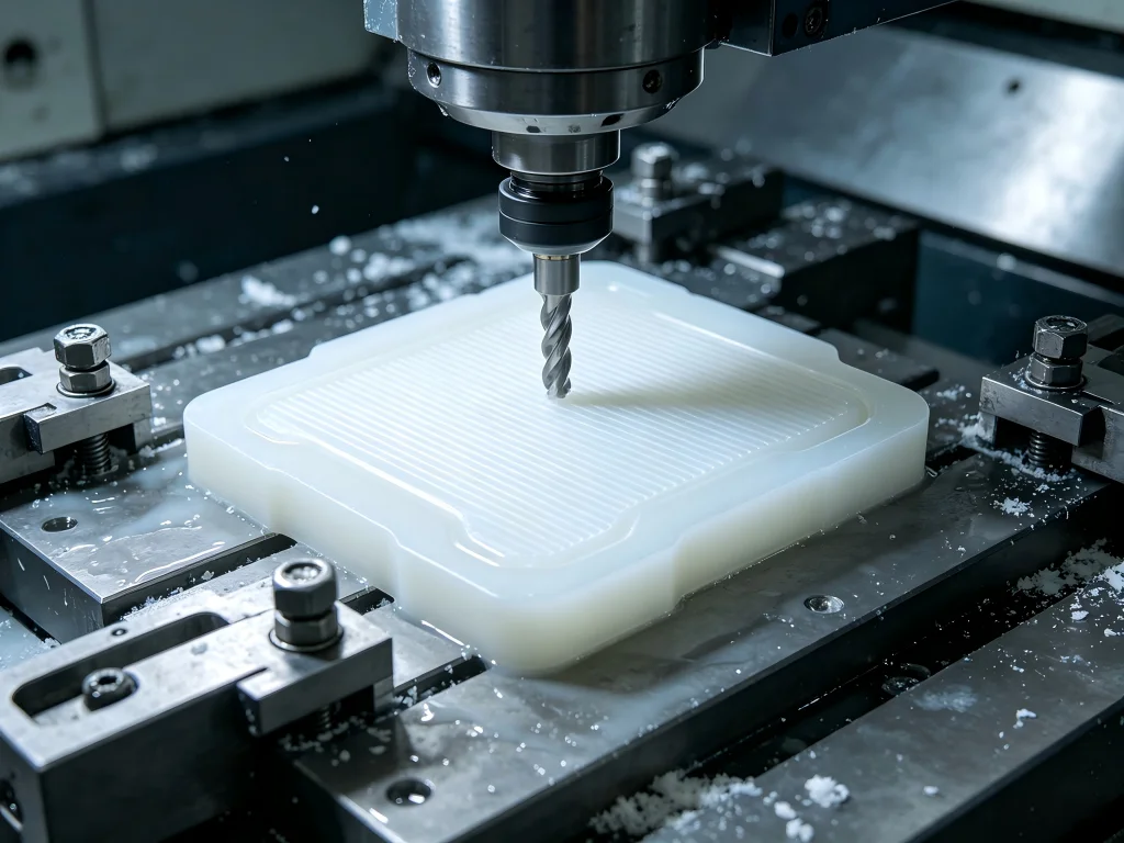
El problema central del PTFE: fácil de cortar, difícil de controlar
Imagine un ingeniero diseñando un asiento de válvula resistente a productos químicos. El plano parece sencillo: un componente redondo de PTFE con un taladro, una cara de sellado, una ranura y varias dimensiones críticas.
El primer prototipo luce excelente.
Entonces comienza la inspección.
El diámetro exterior cambia ligeramente después de que la pieza sale del plato. El taladro no tiene exactamente el mismo tamaño varias horas después. La cara de sellado muestra pequeñas rebabas en los bordes. Aumentar la fuerza de sujeción hace que sea más fácil sostener la pieza, pero la dimensión final se vuelve menos predecible.
Este es uno de los problemas definitorios del mecanizado de precisión de Teflón.
El PTFE es mucho más blando y más flexible que los metales de mecanizado comunes. La pieza de trabajo puede comprimirse bajo la presión de sujeción y recuperarse después de liberarla. Las fuerzas de corte pueden mover paredes delgadas. El calor generado durante el mecanizado puede causar cambios dimensionales temporales. Las virutas largas y continuas pueden complicar las operaciones de torneado. Un filo de corte que aún sería aceptable para el aluminio puede comenzar a empujar o desgarrar el PTFE en lugar de producir un corte limpio.
Eso significa que la fabricación exitosa de PTFE requiere una mentalidad diferente.
En lugar de preguntar solo:
- ¿Qué velocidad del husillo debemos utilizar?
- ¿Qué velocidad de avance debemos programar?
- ¿Qué máquina CNC es la más rápida?
Los ingenieros también deben preguntar cómo todo el proceso controla la deformación mecánica, la temperatura, la geometría de corte, la presión del dispositivo de sujeción, la nitidez de la herramienta, la relajación de la pieza, el desbarbado y la inspección.
¿Qué es el PTFE y por qué se utiliza?
PTFE significa politetrafluoroetileno. Es un fluoropolímero valorado por su baja fricción, resistencia química, propiedades de aislamiento eléctrico, amplia capacidad de temperatura de servicio y comportamiento antiadherente.
Teflon es una marca registrada conocida asociada con materiales fluoropolímeros, mientras que PTFE es la designación genérica del polímero. Para la adquisición de ingeniería, los planos y las solicitudes de cotización normalmente deben identificar el grado real del material en lugar de depender únicamente de un nombre comercial.
El PTFE es atractivo cuando un componente debe funcionar donde los plásticos o metales convencionales pueden crear problemas. Según el grado y la aplicación, los componentes de PTFE pueden proporcionar:
- fricción muy baja;
- fuerte resistencia a muchos productos químicos agresivos;
- aislamiento eléctrico útil;
- baja absorción de humedad;
- comportamiento de superficie antiadherente;
- buen rendimiento en un amplio intervalo de temperaturas;
- compatibilidad con aplicaciones de sellado y deslizamiento;
- maquinabilidad relativamente sencilla.
Estas propiedades explican por qué el PTFE aparece en equipos semiconductores, sistemas de procesamiento químico, bombas, válvulas, instrumentos de laboratorio, equipos eléctricos, conjuntos aeroespaciales, equipos relacionados con la medicina, maquinaria para el procesamiento de alimentos, sistemas de fluidos y automatización industrial.
Sin embargo, varias propiedades que hacen útil el PTFE en servicio también crean desafíos de mecanizado. La baja rigidez significa que la pieza de trabajo puede desviarse. La baja fricción dificulta el agarre del material. Su expansión térmica relativamente alta en comparación con los metales complica el control dimensional. Su blandura puede favorecer la formación de rebabas cuando las herramientas no están suficientemente afiladas.
Por lo tanto, el PTFE demuestra un principio de fabricación importante: una buena maquinabilidad no significa automáticamente una precisión fácil.
¿Se puede mecanizar el PTFE?
¿Se puede mecanizar el PTFE? Sí. El PTFE se puede fresar, tornear, taladrar, mandrinar, roscar, ranurar, refrentar y mecanizar mediante CNC en muchas geometrías personalizadas complejas.
La pregunta de ingeniería más útil es:
¿Se puede mecanizar esta pieza de PTFE en particular de forma repetida hasta las dimensiones, geometría, condición superficial y costo requeridos?
La respuesta depende de la interacción entre el grado del material, la geometría, la tolerancia, la sujeción de la pieza, la secuencia de mecanizado, la temperatura, el herramental y la estrategia de inspección.
Un espaciador de PTFE grueso con tolerancias amplias puede ser sencillo. Un anillo de sellado delgado con estrictos requisitos de planitud puede requerir una ingeniería de proceso sustancialmente mayor, aunque el componente contenga menos material y parezca más simple en un plano.
Esa distinción importa al abastecerse de piezas personalizadas. Cotizar solo por el tamaño de la pieza o el tiempo de mecanizado puede subestimar la dificultad real de fabricación.
Por qué las dimensiones del PTFE pueden cambiar durante el mecanizado
1. Compresión por sujeción de la pieza
Los componentes metálicos generalmente toleran una fuerza de sujeción considerable. El PTFE se comporta de manera diferente.
If chuck jaws, vise jaws, or collets compress the material, machining takes place while the workpiece is temporarily distorted. After the component is released, it may recover toward its original form.
Consider a simplified turned component. The operator clamps a PTFE blank strongly enough to prevent slipping. While compressed, the outside diameter is machined precisely. The dimension looks correct before removal. Once released, elastic recovery changes the geometry.
The machining program may have executed perfectly. The problem came from the mechanical state of the workpiece during machining.
This is why PTFE workholding should aim for sufficient grip with the lowest practical distortion.
2. Thermal Expansion
Machining creates heat through cutting and friction. PTFE responds to temperature changes much more strongly than typical machining metals.
A dimension measured immediately after a warm machining operation may therefore differ from the same dimension after the component stabilizes near the inspection-room temperature.
This becomes increasingly important as:
- the component becomes larger;
- tolerance becomes tighter;
- wall sections become thinner;
- machining cycles become longer;
- inspection temperature differs from production temperature.
For demanding projects, temperature management should be part of the process plan rather than treated as an inspection afterthought.
3. Cutting Force and Deflection
A sharp cutter slices PTFE efficiently. A dull tool may push the material away from the cutting edge before removing it.
That difference affects far more than surface appearance.
Tool pressure may deflect thin walls, distort bores, create poor edge quality, and produce dimensions that become difficult to reproduce from batch to batch.
Sharp cutting geometry is therefore one of the most important practical requirements in precision plastic machining.
4. Material Relaxation
PTFE stock and partially machined components may contain stresses that redistribute when material is removed.
Removing a large amount of stock from one side may allow the remaining material to move. This is especially relevant for large plates, thin sections, rings, asymmetric components, and parts requiring demanding flatness or parallelism.
A roughing-and-finishing strategy may help. Instead of attempting to reach final dimensions immediately, the manufacturer may remove most material first, allow the component to stabilize when appropriate, and then perform controlled finishing operations.
The Five Variables That Usually Decide PTFE Machining Success
Tool Sharpness
Tool condition should receive exceptional attention.
PTFE responds better to cutting than rubbing. Sharp edges can reduce cutting forces and produce cleaner surfaces. As an edge deteriorates, the tool may begin pushing and tearing the polymer rather than slicing it cleanly.
This can lead to:
- fuzzy edges;
- raised burrs;
- poor dimensional repeatability;
- higher heat generation;
- thin-wall deformation;
- inconsistent surface finish.
A supplier experienced with metals but unfamiliar with engineering plastics may underestimate how quickly a seemingly minor tooling issue becomes a dimensional problem.
Workholding Strategy
PTFE is slippery and compliant. Those characteristics create competing requirements.
The fixture must prevent movement, yet excessive force may deform the workpiece.
Possible solutions depend on geometry and may include larger contact areas, purpose-designed soft jaws, controlled collet pressure, supporting mandrels, sacrificial features, vacuum fixtures for suitable flat parts, and machining sequences that preserve support until critical finishing operations are complete.
There is no universal fixture for every PTFE component. Good workholding is geometry-specific.
Control de viruta
PTFE can produce long, continuous chips, particularly during turning. Poor chip management may allow material to wrap around the workpiece or tooling.
Tool geometry, programmed cutting strategy, chip-breaking motions where appropriate, air evacuation, and operator monitoring may all contribute to safer and more consistent production.
Chip control also affects automation. A cycle that produces the correct dimension but requires constant manual removal of stringy chips may not be suitable for economical production quantities.
Temperature Control
The tighter the dimensional requirement, the more important thermal consistency becomes.
Manufacturers may need to consider raw-material storage conditions, machining temperature, cutting-generated heat, stabilization time, inspection-room conditions, and packaging or shipping environments.
This does not mean every PTFE part needs laboratory-level temperature control. It means tolerance expectations should reflect the physical behavior of the polymer.
Inspection Method
Inspection itself can distort a soft polymer.
Excessive measuring pressure from handheld equipment may influence the result on flexible features. Thin rings and walls may deform under contact. Measuring a warm component immediately after machining may create misleading data.
For demanding components, the manufacturer should define not only what will be measured but also when and how it will be measured.
PTFE CNC Machining Methods
Torneado CNC
Turning is widely used for rotational PTFE components such as:
seats, bushings, sleeves, washers, rings, insulators, valve components, spacers, nozzles, seals, and threaded parts.
The challenge usually lies in workholding and dimensional stability rather than raw material removal.
For thin cylindrical parts, support becomes especially important. A component may appear round while restrained and become slightly oval after removal if fixture pressure is excessive.
Fresado CNC
Milling supports rectangular parts, pockets, slots, mounting features, complex profiles, manifolds, guides, electrical components, and custom equipment parts.
Large flat components require careful planning because PTFE does not behave like a rigid aluminum plate. Aggressive clamping can distort the blank before the first toolpath begins.
Machining strategy should therefore consider the entire component rather than treating each feature independently.
Drilling and Boring
PTFE can be drilled, but deep holes, small diameters, concentricity requirements, and thin surrounding walls may increase difficulty.
Sharp tools, effective chip evacuation, controlled heat generation, and appropriate entry conditions could improve hole quality.
Where bore geometry is critical, boring or another controlled finishing operation may provide better results than relying on drilling alone.
Roscado
Internal and external threads can be machined in PTFE. However, engineers should consider the intended load because PTFE threads do not behave like steel threads.
Thread engagement, wall thickness, mating material, repeated assembly cycles, temperature, and long-term creep should all influence the design.
A perfectly machined thread is not automatically a mechanically appropriate thread.
Multi-Axis Machining
Complex PTFE components may contain angled ports, compound surfaces, cross holes, multiple sealing faces, and features positioned around several orientations.
Multi-axis machining can reduce setups. This may be especially useful for flexible components because every additional setup introduces another opportunity for repositioning error or fixture-induced distortion.
PTFE CNC Machining vs Other Engineering Plastics
| Material | Machining Behavior | Dimensional Stability | Key Strength | Typical Concern |
|---|---|---|---|---|
| PTFE | Easy cutting but flexible | Relatively challenging | Chemical resistance and low friction | Creep, deformation and thermal movement |
| POM/Acetal | Very good machinability | Generally better than PTFE | Stiffness and dimensional consistency | Not suitable for every chemical or thermal environment |
| PEEK | Good with correct tooling | High for an engineering polymer | Mechanical and thermal performance | High raw-material cost |
| Nailon | Generally machinable | Environment dependent | Wear resistance and toughness | Moisture absorption |
| UHMW-PE | Soft and machinable | Moderate to challenging | Impact and abrasion performance | Flexibility and burr control |
This comparison shows why material selection should begin with application requirements rather than machinability alone.
If extremely low friction and chemical inertness dominate the design, PTFE may be the better solution. If stiffness and dimensional repeatability are more important and chemical exposure is moderate, an engineer might consider acetal. If temperature and structural performance are critical, PEEK may justify its higher material cost.
Where Precision-Machined PTFE Components Are Used
Chemical Processing Equipment
Chemical resistance is one of PTFE’s strongest advantages. Machined components may appear in valves, pumps, laboratory systems, fluid-control assemblies, chemical handling equipment, and process instrumentation.
Typical components include valve seats, sealing elements, spacers, bushings, guides, insulators, and custom fluid-system components.
In these applications, dimensional accuracy must work together with chemical compatibility. A material may survive the chemical environment but still fail if the sealing geometry is wrong.
Semiconductor Manufacturing Equipment
Semiconductor manufacturing may expose components to aggressive chemicals and demanding cleanliness requirements.
Machined fluoropolymer parts can be used in fluid handling, chemical delivery, wafer-processing equipment, laboratory systems, and insulating applications.
Here, contamination control, traceability, burr control, clean packaging, and material documentation may become as important as dimensional tolerance.
Electrical and Electronic Equipment
PTFE’s electrical insulation properties make it useful for insulating components, supports, spacers, connectors, high-frequency applications, and specialized electronic assemblies.
Complex CNC machining allows insulating components to integrate holes, pockets, channels, mounting features, and alignment geometry into a single part.
Medical and Laboratory Equipment
PTFE may be selected for certain laboratory, diagnostic, fluid-handling, and equipment applications where chemical compatibility and low-friction behavior are useful.
For these markets, supplier quality systems become particularly important. Material traceability, controlled production, inspection documentation, and repeatable processes may be required by the customer’s quality program.
Aerospace and Industrial Systems
PTFE components may function as low-friction elements, insulators, seals, guides, spacers, and chemical-resistant parts in demanding industrial systems.
Engineers should carefully evaluate creep, load, temperature, and dimensional requirements because PTFE is not a universal replacement for structural engineering plastics.
Designing a PTFE Part That Can Actually Be Manufactured
One of the best ways to reduce machining problems happens before the purchase order is issued.
Good DfM can reduce cost more effectively than simply negotiating the machining rate.
Avoid Unnecessary Tight Tolerances
Every tolerance should have a functional reason.
If a non-critical outside profile can operate at ±0.20 mm, specifying ±0.02 mm may add process controls, inspection time, scrap risk, and cost without improving the product.
Reserve demanding tolerances for interfaces that actually influence sealing, alignment, assembly, flow, electrical function, or motion.
Be Careful With Thin Walls
Thin PTFE walls can move under cutting and clamping forces.
If a thin feature is unavoidable, designers may improve manufacturability by adding temporary support, changing the machining sequence, modifying adjacent geometry, or allowing the manufacturer to recommend a fixture strategy.
Specify Critical Geometry Clearly
A ± dimensional tolerance does not automatically control flatness, perpendicularity, cylindricity, or position.
If a sealing face must remain flat or a bore must remain concentric with an outside diameter, communicate those functional requirements explicitly.
This allows the machining supplier to develop the process around what actually matters.
Consider Creep in the Final Application
PTFE can deform over time under sustained load. This is not primarily a CNC problem; it is a material behavior issue.
Engineers designing bolted joints, loaded threads, press fits, sealing systems, and structural interfaces should consider long-term deformation rather than assuming that an accurately machined dimension will remain unchanged indefinitely under load.
Practical Manufacturing Workflow for Precision PTFE Parts
- Review the CAD model and drawing. Identify critical tolerances, thin sections, sealing surfaces, deep bores, threads, and areas vulnerable to deformation.
- Confirm the material specification. Define virgin or filled PTFE, required documentation, color, stock form, and any application-specific requirements.
- Develop the workholding concept. Grip the stock securely while limiting compression and distortion.
- Plan roughing and finishing separately. Leave controlled material for finishing rather than forcing every feature to final size during the first operation.
- Control cutting conditions. Use sharp tooling, suitable geometry, effective chip evacuation, and parameters that limit unnecessary heat.
- Allow stabilization where necessary. Particularly demanding parts may benefit from controlled relaxation before final inspection or finishing.
- Perform controlled inspection. Measure critical dimensions under defined conditions and use appropriate equipment.
- Protect the finished component. Clean packaging can prevent scratches, deformation, contamination, or damage during international shipping.
Installation and Maintenance of Machined PTFE Components
Machining quality can be excellent and the component can still fail if installation creates excessive stress.
PTFE parts should generally be handled as engineered polymer components rather than metal replacements.
Avoid Excessive Assembly Force
Overtightening fasteners can compress PTFE. Press fits that would be routine in metal components may generate unexpected deformation in a polymer part.
Assembly force should follow the engineering design rather than technician intuition.
Protect Sealing Surfaces
A sealing face should remain free from scratches, dents, embedded chips, and handling damage.
Protective packaging and clean assembly procedures may be particularly valuable for fluid and vacuum applications.
Inspect Components During Scheduled Maintenance
Maintenance teams should inspect loaded PTFE components for permanent deformation, wear, surface damage, leakage, and dimensional change where relevant.
Replacement intervals should be based on application conditions rather than assuming that all PTFE components have the same service life.
How Buyers Should Evaluate a PTFE CNC Machining Supplier
Price per component matters, but it should not be the first and only purchasing filter.
For precision polymer components, the supplier’s process knowledge may have a greater influence on total cost than the quoted machine-hour rate.
Ask About Plastic-Specific Experience
A machine shop capable of holding tight tolerances in steel does not automatically understand PTFE.
Ask whether the supplier regularly machines engineering plastics and how it addresses clamping deformation, burrs, thermal movement, and inspection.
Evaluate Inspection Capability
Ask how critical dimensions are verified.
Depending on geometry, inspection may involve micrometers, gauges, optical equipment, height measurement systems, or coordinate measuring technology.
The important question is whether the inspection method is appropriate for a compliant polymer.
Look Beyond the Prototype
A supplier may successfully produce one good prototype manually. Production repeatability is a different question.
Buyers should ask:
Can the fixture repeat? Can tooling condition be controlled? Is inspection documented? Can lot-to-lot material variation be managed? Can the supplier maintain the same manufacturing strategy when quantities increase?
Review Quality Certifications
Quality certifications do not guarantee that every individual component will be perfect, but they can demonstrate that a supplier operates documented systems for process control, traceability, corrective action, and continuous improvement.
This becomes increasingly important for automotive, medical-equipment, semiconductor, aerospace, and other regulated or quality-sensitive supply chains.
Why Choose Jucheng for Custom PTFE CNC Machining?
PTFE manufacturing rewards process control more than aggressive cutting. This makes engineering capability, inspection resources, equipment flexibility, and quality management important supplier-selection criteria.
More Than 150 CNC Machines
Jucheng operates an approximately 8,000-square-meter manufacturing facility with more than 150 CNC machines. This capacity supports prototype work as well as production requirements and allows projects to be matched with appropriate turning, milling, or multi-axis equipment.
25+ Advanced 5-Axis Machining Centers
Complex components may benefit from fewer setups. Jucheng’s fleet includes more than 25 advanced 5-axis machining centers, including Haas and Mazak equipment.
For suitable PTFE geometries, reducing setups could improve positional consistency while reducing repeated clamping and handling.
Engineering and DfM Support
Jucheng provides engineering feedback before manufacturing. This is especially valuable for polymer components because small drawing changes can sometimes create large manufacturing improvements.
Engineers can review tolerance requirements, wall thickness, tool access, corner geometry, workholding surfaces, inspection strategy, and alternative materials before production begins.
IATF 16949 and ISO 13485 Quality Systems
Jucheng operates certified quality systems including IATF 16949 and ISO 13485. These systems support controlled manufacturing and documented quality practices for demanding industrial applications.
Advanced Inspection Resources
Jucheng uses precision inspection equipment including Zeiss CMM systems for dimensional verification.
For PTFE projects, inspection planning should still consider material flexibility and measurement conditions, but strong metrology resources give engineers more options for verifying complex geometry.
One-Stop Manufacturing Support
A project may involve more than cutting the component.
Material sourcing, machining, inspection, documentation, cleaning, packaging, finishing of mating components, and international delivery can all affect procurement efficiency.
Jucheng provides an integrated manufacturing approach designed to simplify this supply chain.
A Realistic PTFE Case: Chemical Valve Seat
Consider a custom PTFE valve seat used in chemical processing equipment.
The initial drawing requires a concentric bore, sealing face, external profile, and groove. The buyer requests very tight tolerances across almost every dimension because the previous supplier experienced leakage problems.
A better engineering approach begins by identifying the actual functional failure.
The sealing surface and relationship between the bore and seat geometry may be critical. Several external dimensions may not affect performance at all.
DfM review could therefore separate functional dimensions from non-critical dimensions.
The manufacturing plan might use controlled workholding, rough machining followed by finishing, sharp dedicated tools, minimal distortion during clamping, controlled inspection conditions, and protected packaging for the sealing face.
This approach attacks the real source of risk instead of simply demanding tighter tolerances everywhere.
The lesson applies beyond valve seats.
Precision machining is not the art of putting the smallest possible tolerance on every dimension. It is the discipline of controlling the dimensions that determine whether the product works.
What Machinists Commonly Say About Teflon CNC Machining
Experienced machinists frequently describe PTFE with a similar contradiction: it cuts very easily, but holding the finished geometry can be frustrating.
Shop-floor discussions repeatedly emphasize three practical ideas.
First, cutting tools should be extremely sharp. When the tool stops slicing cleanly, surface finish and burr control deteriorate quickly.
Second, workholding pressure matters. PTFE may slip when clamping is too light, yet excessive pressure can compress the stock and create dimensional recovery after release.
Third, temperature and measurement timing matter when tolerances become demanding.
These observations align with the underlying material behavior. They also explain why simply copying cutting parameters from another plastic may not solve a PTFE dimensional problem.
Common Mistakes That Increase PTFE Part Cost
Copying Metal Machining Practices
PTFE cannot simply be treated as soft aluminum. Fixture pressure, thermal response, tool geometry, and inspection behavior are fundamentally different.
Over-Tolerancing the Drawing
Extremely tight tolerances increase inspection and process-control requirements. Apply them where they provide functional value.
Ignoring the Final Operating Temperature
A component designed and inspected at room temperature may operate under very different thermal conditions.
Material expansion should be considered during design.
Using Dull Tools
A dull cutter may still remove PTFE, which can hide the problem. The resulting force, heat, burrs, and poor surface quality may make the process unstable.
Measuring Immediately Without Considering Stabilization
For demanding dimensions, measurement timing and temperature can influence results.
Choosing a Supplier Only by Unit Price
A lower quotation provides little value if dimensional variation causes assembly problems, leakage, sorting, rework, delayed production, or rejected shipments.
Total manufacturing risk should be part of supplier evaluation.
FAQ About PTFE CNC Machining
1. Can PTFE be machined with CNC equipment?
Yes. PTFE can be turned, milled, drilled, bored, threaded, grooved, and machined into complex custom components. The main challenge is usually dimensional control rather than cutting difficulty.
2. Is Teflon CNC machining difficult?
The material is generally easy to cut, but precision machining may be challenging because PTFE is soft, slippery, flexible, and sensitive to temperature and clamping pressure. Sharp tooling and carefully designed workholding are particularly important.
3. What tolerance can CNC-machined PTFE achieve?
There is no responsible universal tolerance for every PTFE component. Achievable tolerance depends on part size, geometry, wall thickness, material grade, temperature, fixture strategy, and inspection method. A machining supplier should review the drawing before confirming critical tolerances.
4. Why does my PTFE part change size after machining?
Possible causes include thermal expansion, fixture compression, residual stress redistribution, material relaxation, and measurement conditions. The effect may become more noticeable on large, thin, or tightly toleranced components.
5. What tools are best for machining PTFE?
Very sharp cutting edges and geometries that slice rather than push the polymer generally provide better results. Exact tool selection depends on whether the operation involves turning, milling, drilling, grooving, or threading.
6. PTFE or POM: which is better for CNC parts?
Neither material is universally better. PTFE may be preferred for chemical resistance, low friction, and specialized temperature or electrical requirements. POM generally provides greater stiffness and dimensional stability. Application requirements should determine the choice.
7. Can PTFE parts be used for sealing applications?
Yes. PTFE is widely used in sealing and valve applications. However, sealing performance depends on material grade, surface geometry, pressure, temperature, mating surfaces, creep behavior, and overall seal design.
8. What information should I send for a PTFE CNC machining quote?
Send a 3D CAD model when available, a 2D drawing showing critical tolerances and GD&T requirements, material grade, quantity, surface requirements, inspection expectations, certification requirements, and application information that may influence manufacturing.
From CAD File to Reliable PTFE Component
The question is not simply whether PTFE can be cut by a CNC machine. It can.
The harder question is whether a manufacturer can repeatedly transform a flexible, low-friction, temperature-sensitive polymer into a component that remains within functional requirements after machining, inspection, shipping, assembly, and service.
That requires coordination between design, material selection, workholding, tooling, machining sequence, temperature management, inspection, and quality control.
For engineering teams, the most effective sourcing strategy is therefore to involve the machining supplier early. A useful DfM discussion could eliminate unrealistic tolerances, improve fixture access, protect critical sealing surfaces, reduce setups, and lower production cost before the first PTFE blank reaches a CNC machine.
Request a PTFE CNC Machining Quote
If you are developing PTFE valve components, seals, bushings, insulators, semiconductor equipment parts, fluid-handling components, laboratory equipment, or other custom precision plastic parts, Jucheng can review your design and manufacturing requirements.
Submit your CAD model, engineering drawing, material specification, target quantity, and critical tolerance requirements through Mecanizado CNC Jucheng.
For related manufacturing resources, you may also explore Jucheng’s capacidades de mecanizado CNC, engineering materials, design guides, and precision manufacturing services.
For additional material-property validation during final engineering design, buyers should also consult authoritative polymer-material data and the specific PTFE grade manufacturer’s technical datasheet. External engineering references should be used together with application-specific testing rather than as a substitute for validation.