
CNC part marking requirements should state what identity the part needs to carry, where the mark belongs, how it will be made, and how the result will be accepted. A note that says only “mark part” leaves open whether the text is a part number, a serial number, a revision, or a lot code—and whether the mark may touch a fit, sealing face, or finished surface.
Decide first whether the mark is for identification, traceability, assembly orientation, or a machine-readable code. Then place it in the product definition with enough detail for a supplier to quote and verify it. The method and exact dimensions depend on the material, geometry, finish, and customer requirements.
Contenido
- A mark identifies a part; it does not replace its records
- Locate the mark away from working surfaces
- Choose a method after material and finish are known
- Put marking in the process sequence
- Treat a 2D code as a readable feature
- Build a callout a supplier can quote
A mark identifies a part; it does not replace its records
A fixed part number identifies a design. A serial number identifies an individual unit; a lot or batch code links a group of parts to a production or material record. A revision identifies the approved product definition. These fields are not interchangeable, and adding all of them to every part can create clutter without improving control.
Decide what a downstream user must learn from the physical mark and what can remain in the certificate, inspection report, traveler, or shipment label. If the goal is to trace material or inspection history, define the link between the identifier and the records rather than relying on the code alone. The CNC traceability guide explains how identifiers connect to stock lots and dimensional evidence.
Locate the mark away from working surfaces
Mark location is an engineering decision. A shallow mark on a nonfunctional face may be harmless, while the same mark on a bearing journal, seal land, datum, thread, or thin wall can interfere with fit, contact, inspection, or appearance. The drawing should identify the permitted region with a view, leader, or datum-based location when the position matters. “Near the edge” is difficult to reproduce if the edge is not defined or the part has several orientations.
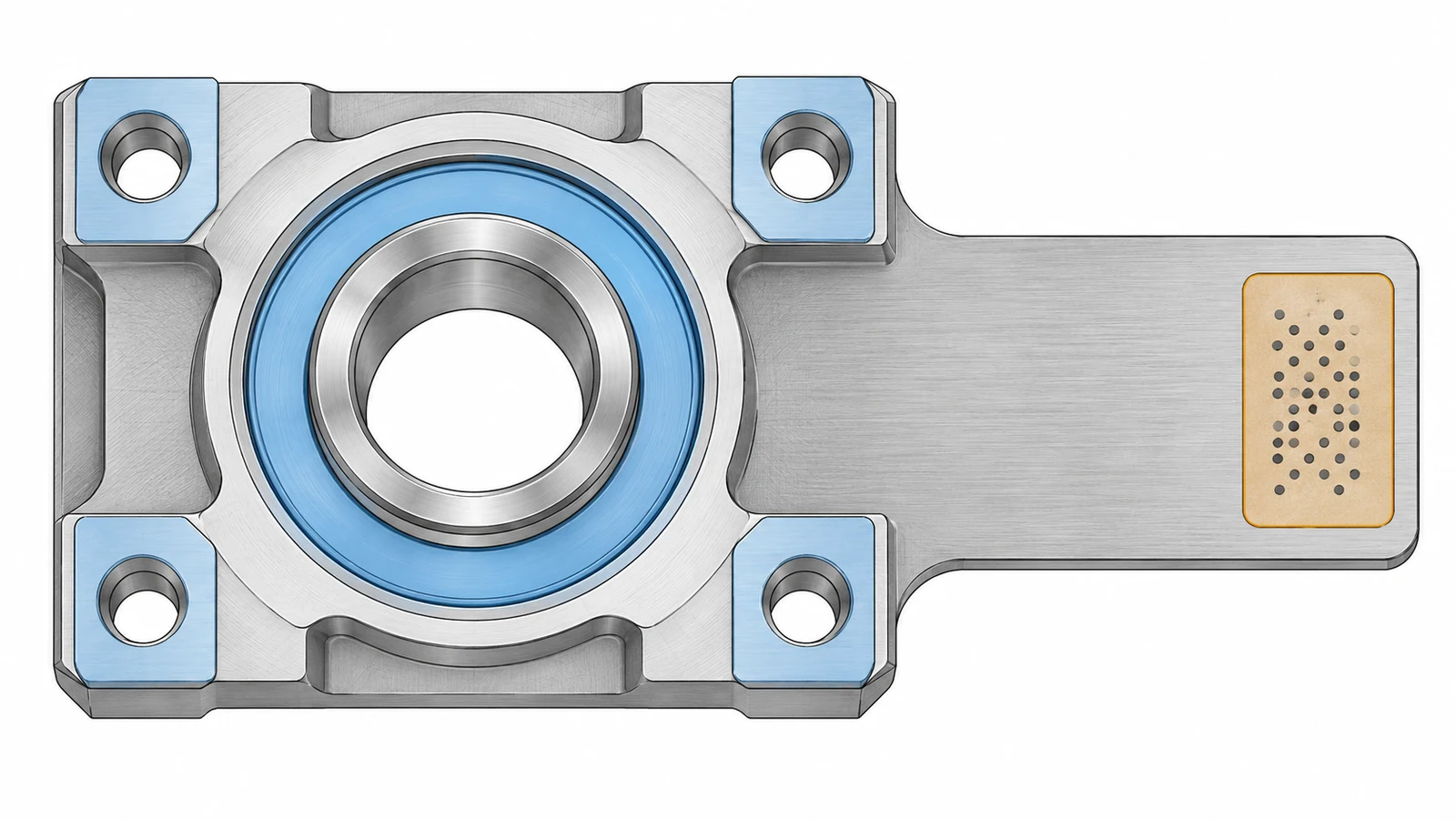
Check the mark against the assembled condition, not only the isolated part. A label or code can be covered by a bracket; a raised or recessed mark can collect debris; a character line can cross a sealing face. If marking must avoid a protected zone, identify that zone explicitly and confirm that the chosen location remains accessible after assembly and finishing.
For aerospace or regulated work, use the customer’s drawing and applicable specification as the controlling requirements. The marking examples in an industry-specific inspection plan are not a universal requirement for every CNC component.
Choose a method after material and finish are known
Laser marking, laser engraving, mechanical engraving, dot-peen marking, stamping, etching, and labels create different surface conditions. Their suitability depends on material, hardness, wall thickness, coating, corrosion exposure, code size, and whether the mark must remain legible through service. A method that removes material may not be acceptable on a thin section or a critical surface; a surface mark may be obscured by a later treatment.
Do not specify a process only because it is familiar. Ask whether the mark needs to be permanent, readable without magnification, machine-readable, or removable during repair. If a drawing names a specific method, the supplier should confirm that it is feasible for the material and geometry before release. The site’s laser engraving service page describes that service intent; a project-specific marking method and scope still need confirmation against the part requirements.
Put marking in the process sequence
Timing affects both legibility and the finished part. A mark applied before machining may be cut away; one applied before anodizing, plating, painting, or polishing may become less visible or change in appearance. Applying it afterward can protect the code from being obscured, but may place the marking operation on a finished surface that needs special handling.
State whether marking occurs before or after each relevant finish and inspection step. If the part may be reworked, decide whether the old mark must be removed, replaced, or retained with a documented disposition. The surface-finish guide covers how finishing changes a part’s surface; the drawing should make the relationship between finish and mark clear.
Treat a 2D code as a readable feature
A Data Matrix or other 2D symbol needs more than a blank square on the model. Define the payload, required human-readable text, permitted location, orientation, size range, and how readability will be checked when those details matter. A code that scans only on a clean prototype may fail after coating, curvature, glare, abrasion, or production variation. The buyer and supplier should use the required application standard and verifier criteria rather than inventing a grade from a generic example.
Keep payloads concise and controlled. Include only fields needed by the downstream system, and decide how serial values are assigned and checked for duplicates. If the symbol is tied to inspection or material records, specify where the lookup data lives and who maintains it.
Build a callout a supplier can quote
A useful marking note identifies the content, method or allowed method range, location, size or legibility requirement, orientation, process timing, and inspection evidence needed for the application. It should also name any surface that must remain unmarked. The required detail varies: a simple part number on a noncritical face needs less control than a serialized code on a finished component.
For example, a drawing may use a project-specific note in this form:
MARK: [required content or data structure] BY [approved method]; LOCATE PER [view/detail]; ORIENT AS SHOWN; APPLY [before/after named finish]; VERIFY [legibility or code criterion]. DO NOT MARK [protected surfaces].
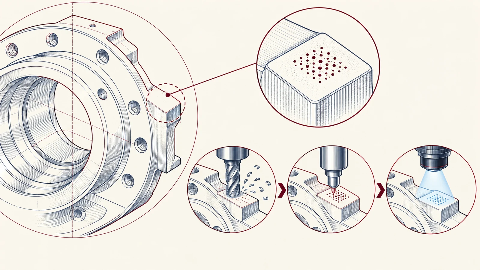
This is a structure for communicating intent, not a universal specification. Replace each bracket with the customer-approved requirement and confirm that the method is available for the part before the drawing is released. The broader CNC quality-control guide describes how drawing requirements should connect to inspection and release evidence.
Clear marking requirements prevent a small identification feature from creating a larger fit, finish, or traceability problem. Define what the mark must prove, protect the surfaces that perform a function, and agree how the finished mark will be checked.