
A CNC part that changes size during a run may be responding to thermal growth in the machine, the workpiece, or both. Machine thermal drift is a gradual change in the relative position of the tool and workpiece as heat from the spindle, axes, cutting process, coolant, or room conditions changes the machine structure. It is not the same as measuring a hot part and assuming its room-temperature size. Separate those two effects before changing offsets or blaming a material lot.
For a buyer, the practical issue is repeatability across the run: does the first piece differ from later pieces, does the error follow one axis or feature, and does it return after a shutdown? A trend with time suggests a different control problem from a constant offset or a part that was measured at inconsistent temperatures.
Separate machine movement from part temperature
Thermal drift describes a changing machine coordinate relationship. As heat enters a spindle, bearings, motors, ball screws, guideways, casting, or fixture, components expand at different rates and in different directions. The tool center point can therefore move relative to the workpiece even when the program and nominal offsets have not changed. The size and direction depend on the machine design, duty cycle, environment, and measurement method; there is no universal warm-up time or correction value that fits every machine.
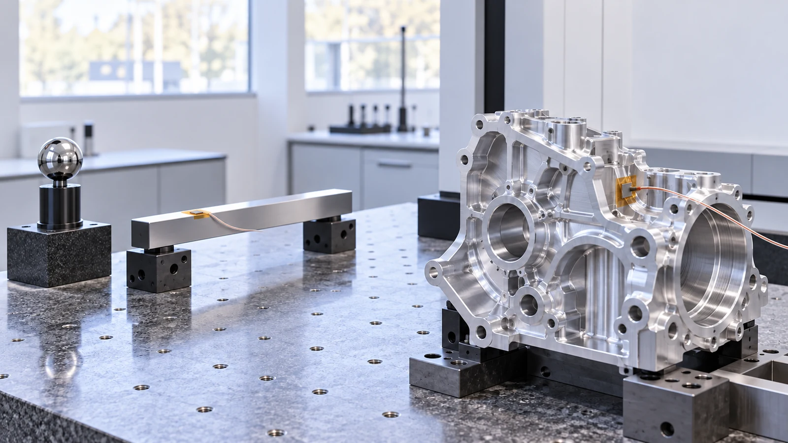
Workpiece temperature creates a second effect. A metal part measured soon after cutting may not have the same dimension it will have after stabilizing in the inspection environment. If the CMM, comparator, or hand instrument is in a different temperature condition, the measured result may shift again. These effects can overlap, so a “warm part” explanation does not prove the machine is thermally stable.
| Padrão observado | Likely question | Useful separation check |
|---|---|---|
| First-off parts differ, then dimensions trend and settle | Is the machine approaching a repeatable thermal state? | Record elapsed run time and the same feature on successive parts |
| Several features shift together in one direction | Is a shared axis, fixture, or datum moving? | Compare features tied to the same machine axis and setup reference |
| Only one thin or asymmetric feature changes after cutting | Is stress release or local part heating more likely? | Compare free-state geometry after a consistent stabilization interval |
| Inspection readings vary between operators or instruments | Is measurement temperature or method inconsistent? | Standardize part condition, datum, instrument, and contact points |
This is a diagnostic map, not a substitute for machine calibration or a measurement-system study. It helps prevent the common mistake of applying a machine offset to compensate for a part that simply has not reached the agreed inspection condition.
Follow the heat path through the process
Begin with the duty cycle. A spindle that has been idle, a machine that has just started, and a machine that has run a long sequence of high-load cuts may not be in the same thermal state. Axis motion, spindle speed, cutting load, coolant flow, and the distribution of operations across the work envelope all affect heat generation and removal. A test on one feature near the center of travel may not represent a feature machined at the edge of the working envelope.
Next inspect the workholding and coolant conditions. A fixture can warm unevenly; coolant temperature and flow can change between shifts; chips packed around a fixture can alter local heat transfer or prevent the part from seating consistently. These conditions do not prove a machine error, but recording them can explain why two nominally identical runs behave differently.
Consider operation order as well. Roughing can heat and stress the work differently from a light finishing pass. If a critical feature is cut early and then the part experiences substantial heat or stock removal elsewhere, a later measurement may show a change unrelated to the original tool offset. A stable process route places critical datums and finishing operations where their thermal and mechanical context is understood.
Record a time-based error pattern
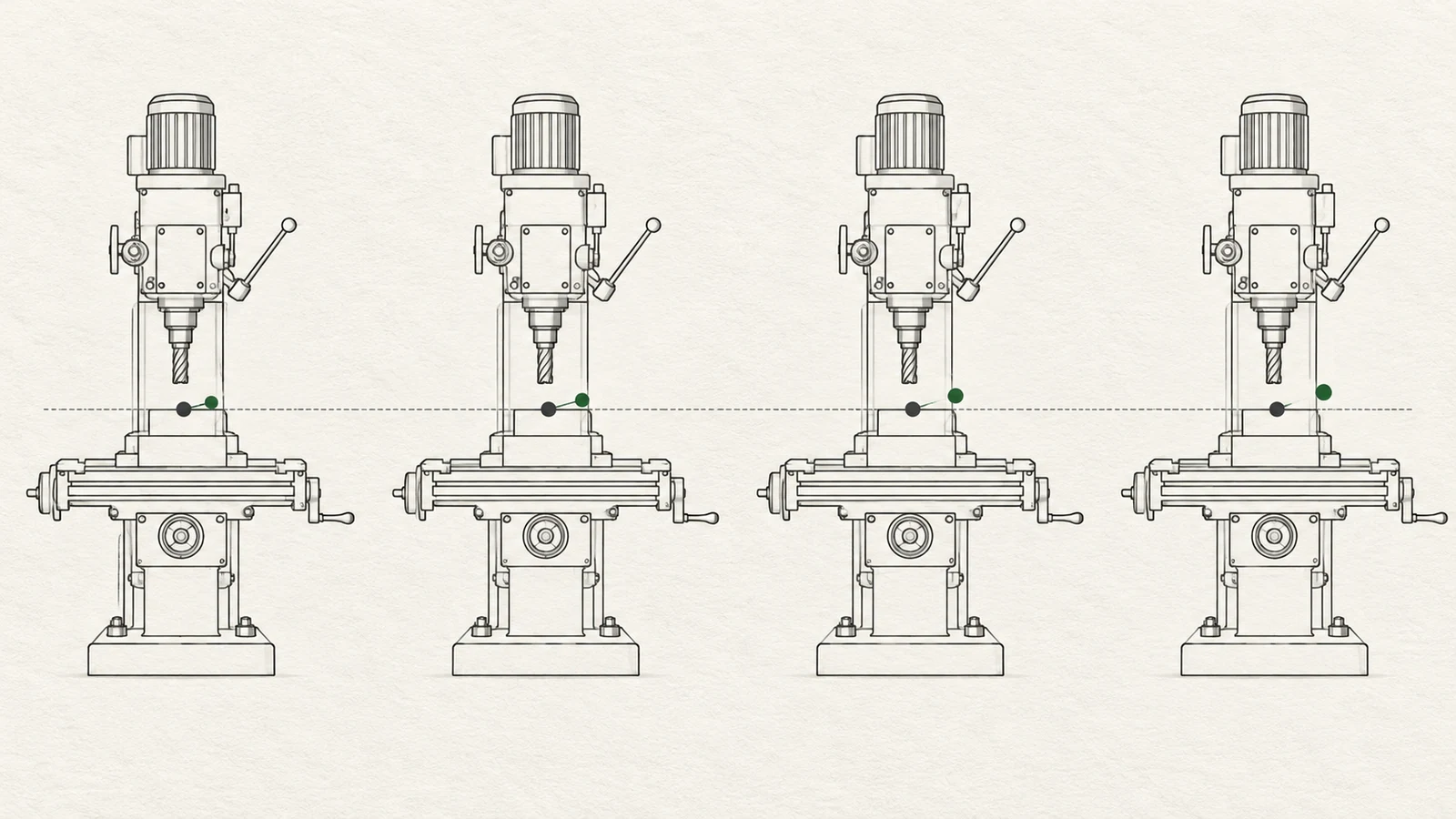
A useful investigation starts with repeatable observations rather than repeated offset edits. For a controlled check, keep the program, tool, fixture, material lot, coolant condition, and measuring method fixed. Record the machine start state, elapsed time, spindle or axis activity that matters to the operation, and the measured result for selected features. Use the same datum and measurement locations each time.
- Define which dimensions are drifting and how they relate to machine axes and datums.
- Measure a first-off part and subsequent parts at planned intervals without changing the process.
- Where practical, remeasure a part after it reaches the agreed inspection condition to estimate the workpiece-temperature contribution.
- Compare the trend across a fresh start and a warmed run; repeat only if the setup and method remain controlled.
- Escalate persistent or non-repeatable behavior for machine diagnosis rather than compensating blindly in the part program.
The aim is not to prescribe a universal thermal compensation scheme. It is to determine whether the pattern follows time, machine position, part geometry, or inspection condition. For parts where the drawing makes a tight relationship between multiple features important, clarify the datum scheme and inspection method with the supplier. The site’s abordagem de qualidade is the relevant context for how acceptance requirements should be defined and checked.
Choose controls that match the source
If the error follows machine warm-up, a controlled warm-up routine or a validated compensation strategy may improve consistency, but only after the shop confirms the pattern on the actual machine and job. If the error follows a particular axis position, machine geometry or axis behavior may need investigation. If only the workpiece changes after cutting, review stock condition, operation sequence, clamping, and stabilization instead.
For procurement, provide the drawing revision, critical dimensions, datums, quantity, material condition, and acceptance method. State whether first-piece approval, periodic checks, or lot records are required. Avoid writing “no thermal drift” as an acceptance criterion; identify the feature, measurement condition, and permitted dimensional boundary instead. A clear plan lets the supplier choose an appropriate CNC machining route without implying a guaranteed universal tolerance.
Perguntas frequentes
How long should a CNC machine warm up?
There is no single duration that applies to every machine and job. The needed routine depends on machine design, ambient conditions, operating cycle, and the tolerance relationship being controlled. Use a validated process rather than adopting an arbitrary time as proof of stability.
Can thermal drift be fixed by changing the work offset?
A work offset can compensate for a stable, understood shift, but it can make a changing or feature-specific error worse. First determine whether the variation follows machine time, axis position, workpiece temperature, or measurement conditions.
Is thermal drift the same as workpiece distortion?
No. Machine thermal drift changes the tool-to-workpiece coordinate relationship. Workpiece distortion can result from temperature gradients, clamping, residual stress, or material removal. Both can affect dimensions, but they require different checks.