
Thread pitch diameter is the dimension that largely governs how external and internal thread flanks engage. A part can pass a major-diameter check and still bind, feel loose, or fail a functional gauge because pitch diameter, pitch, flank angle, lead, or form is wrong. Select an inspection method that matches the thread type, tolerance class, production stage, and acceptance decision; one measurement does not verify every thread characteristic.
For many purchasing and receiving checks, a calibrated GO/NO-GO thread gauge is the practical functional screen. When a numeric pitch-diameter value or process adjustment is needed, a measurement method such as the three-wire method for external threads may be more informative. Internal threads require suitable plug gauges or specialized measurement equipment. The drawing and applicable thread specification must state the intended system and class.
What pitch diameter controls
The pitch diameter is an imaginary cylinder on a thread where the thread ridge width and groove width are equal under the defined thread geometry. It is not the crest diameter or root diameter. For a mating pair, pitch diameter influences flank contact and clearance, while pitch, included angle, lead, thread form, and surface condition also affect assembly.
That is why a caliper reading across the thread crests is not a pitch-diameter inspection. Major diameter can help identify a gross size issue or damage, and minor diameter can matter for internal clearance or root geometry, but neither alone confirms the functional fit. An acceptance plan should identify the thread callout, tolerance class, gauge system, and whether a functional gauge or numeric result is required.
If thread machining is part of the manufacturing route, the site’s خيارات اللولبة و custom thread capability pages are relevant process context. They do not replace a complete drawing callout; provide the thread standard, nominal size, pitch, hand, class, and any special form requirement.
Functional gauges answer a pass/fail question
A GO gauge checks whether the thread can accept a correctly sized functional mating form under the prescribed method. A NO-GO gauge checks a different boundary and should engage only within the limit allowed by the applicable standard. The details depend on whether the thread is internal or external and on the gauge standard, class, and condition. Use the gauge instructions and governing specification rather than applying a universal turn count from memory.
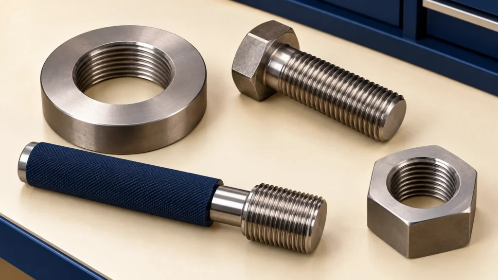
Gauge condition matters. Keep gauges clean, protected, and within calibration; check for wear, damage, temperature effects, and correct handling. A damaged gauge or excessive force can create a false rejection or damage the work. Record gauge identification and calibration status when traceability is required.
Three-wire measurement for external threads
The three-wire method measures an external thread over precision wires placed in the thread grooves. A micrometer measures across the wires, and the result is used with the thread pitch and flank angle to determine pitch diameter. It is useful when a numeric value is needed for process setup, tool wear monitoring, or troubleshooting a fit problem.
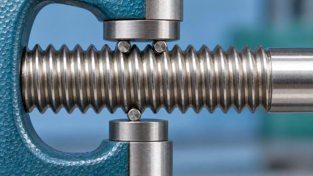
Use the correct calculation or instrument function for the specified thread form. Formulas for a 60-degree Unified or metric thread do not automatically apply to pipe threads, trapezoidal threads, rounded profiles, or special forms. Allowance, truncation, coating, and tolerance class can change what the accepted value means. When the calculation is close to a limit, account for instrument uncertainty and measurement repeatability.
Checking internal threads
Internal threads are commonly screened with calibrated GO and NO-GO plug gauges selected for the specified thread system and class. These gauges provide a functional check but may not tell the inspector the numeric pitch diameter. If the application requires a reported value or detailed diagnosis, use a suitable thread measuring instrument, calibrated thread wires or balls designed for internal measurement, or a coordinate method validated for the geometry and tolerance.
Access and depth influence the method. A gauge may check the entrance but not a long thread’s full length if the part or gauge design prevents proper engagement. Cross holes, blind bottoms, coatings, and runout reliefs can complicate evaluation. State the inspection depth and functional engagement zone on the drawing or inspection plan where it matters.
Avoid the common measurement traps
- Mixing standards: Do not measure a Unified callout with a metric assumption or vice versa; confirm nominal size, pitch, series, class, and tolerance system.
- Using crest diameter as a substitute: Major diameter is not pitch diameter and cannot prove flank fit.
- Ignoring burrs and debris: A burr at the thread start or chips in a blind hole can stop a gauge before the functional thread is evaluated.
- Forcing a gauge: Excessive torque can mask the boundary or damage the part and gauge.
- Overlooking coating: Decide whether threads are inspected before or after plating or coating and account for any specified allowance.
- Reporting false precision: A numeric result is useful only when the measurement method, calibration, uncertainty, and conditions support its resolution.
Build an inspection plan around risk
For a stable production feature, a functional gauge may be sufficient at the agreed sampling rate, with setup verification and gauge control documented. For a new tool, a critical fastener, a sealing interface, or a recurring fit issue, combine functional gauging with a numeric method and inspect more than one location. If the thread is safety-critical or governed by a customer specification, follow the specified control plan and approved measurement procedure.
The inspection record should identify the exact drawing revision, thread callout, gauge or instrument, calibration status, measurement location, coating condition, and result. Keep the first-piece check tied to the tool, machine, and process revision that produced it. This lets engineering distinguish a machining adjustment from a measurement-method mismatch.
الأسئلة الشائعة
Can a thread plug gauge tell me the exact pitch diameter?
Usually it provides a functional pass/fail result rather than a numeric pitch-diameter value. Use a suitable dimensional method when the actual value is needed for diagnosis or process control.
Can I check pitch diameter with calipers?
No. Calipers can measure accessible major or minor diameters within their limits, but they do not directly measure thread pitch diameter or verify full thread fit.
Does a GO gauge check every thread feature?
It checks functional engagement according to its design and governing standard. It does not necessarily isolate pitch diameter from lead, angle, form, burr, or damage, so additional measurements may be needed when a part fails.