
Pump housing bore alignment should be specified from the shaft and bearing arrangement the housing must support, not from whichever outside face is easiest to measure. The drawing needs to show how bearing seats, seal bores, register faces and impeller-related features relate to a functional axis, and whether acceptance applies to a loose housing or an assembled condition. A bore can meet its diameter limit yet still sit off-axis or at the wrong angle. Define the relationship first, then choose a machining and inspection sequence capable of checking it.
Trace the rotating assembly through the housing
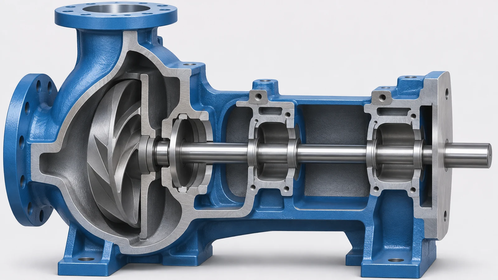
Start with the mechanical chain: shaft, bearings, seals, housing registers and the impeller interface. Identify which housing bores support the shaft, which faces locate bearing or seal components, and which features control axial position. The impeller is mounted on the shaft, so its working position depends on the entire chain, not on one isolated cavity dimension.
Separate radial alignment from axial placement. A bearing bore may establish the rotation axis, while a shoulder or cover face controls the stack along that axis. A seal seat can need both relationships. Avoid a broad note that implies every bore, counterbore and pocket shares the same control.
Build datums around the supported shaft axis
Use datum features that represent the installed housing. A mounting surface or split joint may establish orientation; a bearing seat can establish the axis; a bolt pattern or dowel can set clocking and assembly position. Select the primary reference from the machine interface, not a cosmetic wall or unmachined casting surface unless that surface truly locates the part.
For multiple bearing seats, define coaxiality or axis relationships so they can be interpreted and measured under the specified condition. If the design uses a cartridge, liner or replaceable insert, clarify whether the datum applies to the housing seat, installed insert or final bearing axis. Fit and assembly can move or distort the supported feature, so the inspection basis matters.
موقع 5-axis impeller machining page covers related component interfaces; this article is limited to housing geometry and its inspection definition.
Machine related seats in a controlled sequence
Plan how the workpiece is located before cutting begins. Roughing, stress release, finish machining and part removal can change a casting or thin housing’s shape. Finishing related bores in one setup can preserve their relationship; if a transfer is necessary, the locating method should re-establish the same functional datums. A practical pump housing bore alignment plan preserves these functional relationships through the chosen setup and confirms them after any operation that can release casting stress.
Clamping is part of the process definition. A housing can deflect against an uneven support or when tightened at a few points. If it springs after release, dimensions taken while clamped may not predict the free or installed state. Identify the condition that matters, and use an inspection fixture that reproduces it without imposing unintended force.
Machining accessibility also affects sequencing. A deep bearing seat, seal counterbore and impeller cavity may call for different tool access or orientations. The goal is not to force every feature into one setup, but to prevent datum drift where the functional axis is transferred between operations.
Measure more than bore diameter
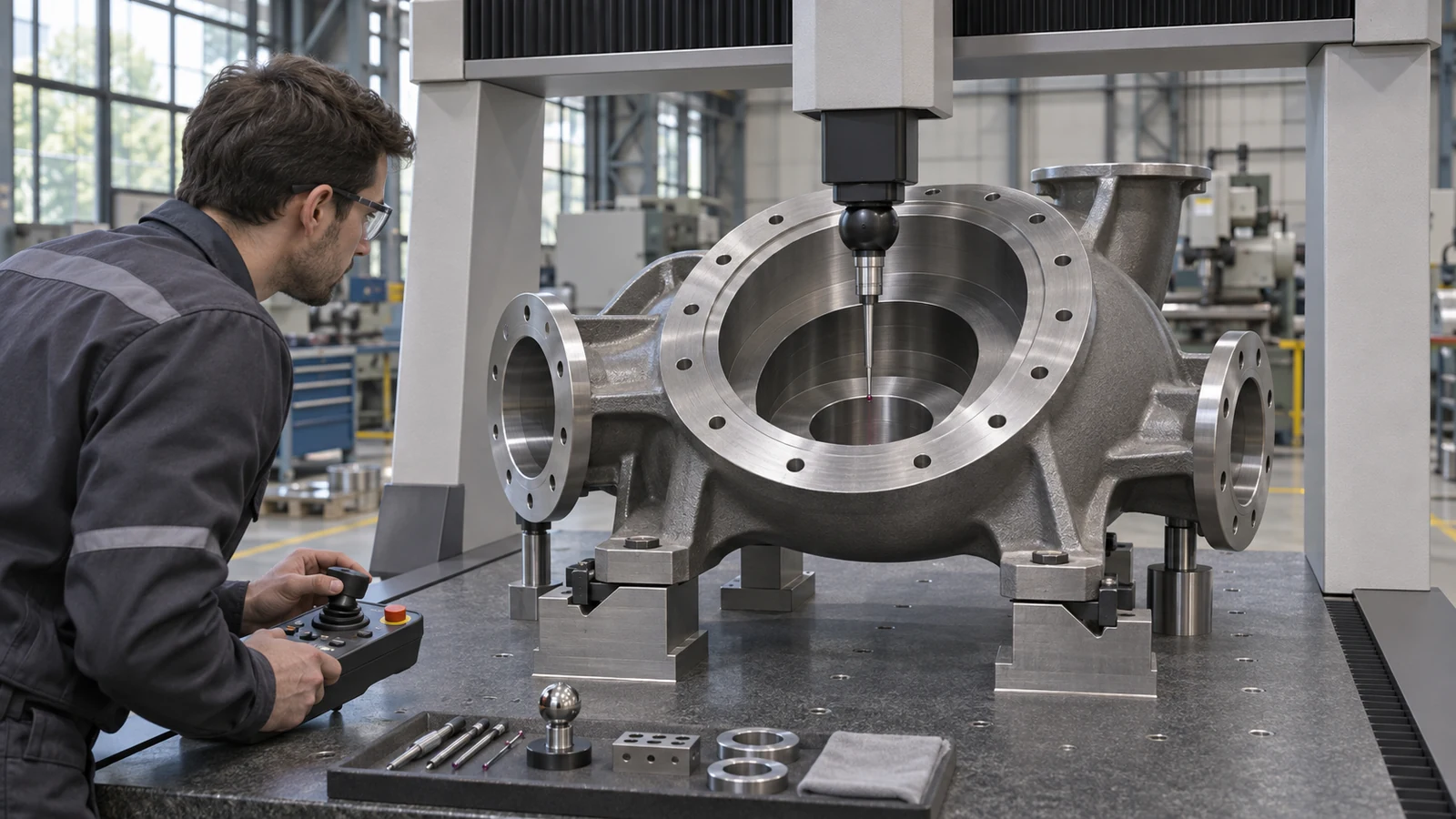
A complete check may include bore size, form where specified, axis location, angular relationship, shoulder position and distance between interfaces. Which characteristics apply depends on the design. A plug or air gage can address size but may not establish a relationship to another bore or face. A coordinate-based inspection can evaluate several relationships if the part is aligned to the correct datum and the measurement reaches relevant depths.
| الميزة | Drawing intent to clarify | سؤال الفحص |
|---|---|---|
| مقعد المحمل | Fit, axis and reference condition | Is size checked separately from axis location? |
| Seal bore or face | Alignment and axial seat | Does measurement relate it to the supported shaft axis? |
| Cover or split interface | Joint condition, dowels and fasteners | Is the housing checked loose or assembled? |
| Impeller-related register | Axial position and runout relationship | Does the setup represent the assembled stack? |
Do not convert a system requirement into an arbitrary tight tolerance on every feature. The designer should identify dimensions that control fit, seal function, rotor clearance or assembly, then allocate measurable limits to them.
Keep alignment separate from pump qualification
Correct bore relationships support assembly, but they do not certify hydraulic performance, leakage, vibration, efficiency or material suitability. Those outcomes depend on impeller design, clearances, balance, bearings, seals, operating fluid, speed and test conditions. State who owns each acceptance test and which records are required. A CNC inspection report documents specified geometry; it should not be presented as a pump performance test unless the responsible party performed that test.
Distinguish a manufacturing alignment problem from wear or assembly damage found during service. Repair decisions require the pump model, drawing, condition and OEM limits. This is a drawing and machining-planning guide, not a repair procedure or universal tolerance schedule.
Give the supplier a usable inspection definition
Include the current housing model and revision, datum scheme, bearing and seal interfaces, fit intent, assembly condition, critical axis relationships, finish requirements and inspection records. Identify whether inserts, sleeves or bearings are supplied with the housing and who installs them. If inspection takes place with a cover or split case installed, define the fasteners, sequence and condition that make the result repeatable.
Before release, review each callout against the intended measurement. If a feature is inaccessible for direct probing, agree on the gage or fixture and its datum transfer before production. A clear drawing helps plan the route; a clear acceptance plan helps distinguish a real alignment issue from a difference in measurement setup. The final pump housing bore alignment review should confirm that each callout and measurement method describes the same assembled or free-state condition.
For general component machining context, see the site’s تفريز CNC page. Actual scope and acceptance remain drawing-specific.