
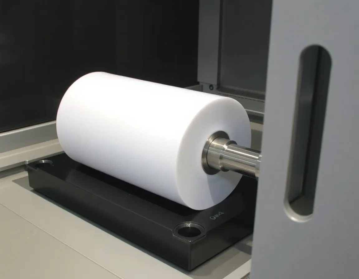
Plastic rollers are deceptively simple components. At first glance, a machined roller looks like a cylinder with a bore and perhaps a few grooves—hardly the stuff of engineering drama. Yet in industries ranging from packaging and printing to textile manufacturing and medical device production, these components quietly determine whether a production line runs smoothly or grinds to a halt. A roller that is out of round by a few thousandths of an inch, or one that develops a subtle taper along its length, can wrinkle film, misalign web tension, or introduce vibration that ripples through an entire machine.
Plastic roller machining is the discipline of turning polymer stock—typically acetal (POM), PTFE, nylon, UHMW-PE, PEEK, or polycarbonate—into precision cylindrical components. Compared with metal, plastics demand a different mindset: they deflect under cutting pressure, they expand with heat, they chip rather than curl, and they can stress-crack weeks after the tool has been put away. The five secrets below separate rollers that perform flawlessly for years from those that become expensive scrap.
Secret One: Understand the Material Before the First Cut
Every machining decision flows from the polymer you choose. A machinist who treats acetal like aluminum will produce a roller that measures correctly on the bench and fails on the machine. Material behavior governs tool geometry, speeds, feeds, fixturing, and even the order of operations.
Know Your Polymer's Personality
Acetal (POM) is the workhorse of roller machining—stiff, dimensionally stable, and machinable to tight tolerances. It also has a low melting point and a tendency to chip at cutter exit. UHMW-PE offers outstanding wear resistance and low friction but is soft and prone to pushing away from the tool, demanding razor-sharp cutters and light radial engagements. PTFE is chemically inert and slippery but creeps under load and deforms with minimal clamping pressure. PEEK handles high temperatures and aggressive chemicals but is expensive enough that a scrapped roller hurts. Náilon absorbs moisture and changes dimensions accordingly, which matters enormously for rollers used in humid environments or wet processes.
Account for Thermal Expansion and Moisture Uptake
Plastics expand roughly five to ten times more than steel per degree of temperature change. If you machine a 300 mm diameter acetal roller at 20°C and it operates at 40°C, the diameter can grow by well over half a millimeter. Similarly, nylon components can swell measurably in humid air. The secret is to machine at a temperature close to the service environment and to specify tolerances that acknowledge these shifts rather than pretending they don't exist.
- Condition stock at the shop's ambient temperature for at least 24 hours before machining.
- For moisture-sensitive nylons, dry the stock and machine promptly, or specify moisture-conditioned tolerances.
- Document the reference temperature on the drawing so future replacement rollers match the original.
Secret Two: Master the Cutting Strategy for Plastics
Plastic roller machining rewards sharp tools and disciplined parameters. Dull cutters generate heat, heat softens the polymer, and softened polymer smears, tears, or welds itself to the tool. The result is a roller with a rough, gummy surface and internal stresses that will haunt you later.
Tooling Choices That Matter
Use high-speed steel or polished carbide tooling with high rake angles and generous clearance. For turning operations, a sharp positive-rake insert designed for aluminum often works well on plastics. For boring the roller's bore—arguably the most critical feature—use boring bars with minimal overhang to reduce deflection. Avoid coated inserts designed for steel; the coatings can increase friction and heat. For drilling long through-bores, use parabolic-flute drills and peck to clear chips frequently, since plastic chips tend to pack rather than eject.
Speeds, Feeds, and the Heat Problem
There is no universal recipe, but the governing principle is constant: remove material quickly enough to avoid rubbing, but not so aggressively that heat builds. Rubbing is the enemy—a tool that skims the surface without cutting generates friction that melts and smears the polymer. Favorable chip loads keep the cutter engaged and the heat in the chip rather than the workpiece.
- Use climb milling on CNC operations to improve surface finish and reduce edge chipping.
- Keep coolant or air blast directed at the cut to control temperature; compressed air is often preferable to flood coolant for porous or hygroscopic plastics.
- Take a light finishing pass—0.1 to 0.25 mm depending on material—to achieve the final dimension and surface quality.
- Never let the tool dwell; continuous engagement beats hesitation every time.
Secret Three: Fixture and Support to Defeat Deflection
Plastic is far less stiff than metal. A long, slender roller machined between centers will deflect away from the tool, producing a barrel-shaped or tapered profile that no amount of measurement at the ends will reveal. Support and fixturing are where amateurs and professionals part ways.
Support the Work Along Its Length
For long rollers, use a steady rest or follow rest to support the workpiece near the cut. For thin-walled tubes, consider machining on a mandrel that supports the bore, or use expanding arbors that distribute clamping force evenly. Chuck pressure must be gentle—over-tightening a plastic tube will leave permanent ovality, and the damage may only reveal itself after the part relaxes.
Sequence Operations to Preserve Accuracy
Machine the bore and the outside diameter in a logical sequence that maintains concentricity. A common approach is to rough both features, allow the part to relax and cool, then finish-machine the bore first and use it as the reference for finishing the OD. If the roller mounts on bearings, bore roundness and cylindricity matter as much as diameter—an out-of-round bore transmits vibration directly into the roller surface.
Secret Four: Control Stress, Both Thermal and Residual
Machined plastics carry residual stress from the original extrusion or casting process, and machining adds more. When material is removed unevenly—say, milling a keyway on one side of a roller—the balance of internal stress shifts, and the part can bow. The same happens when one side of a roller heats up more than another during cutting.
Practical Stress-Relief Tactics
- Rough, then rest, then finish. Remove the bulk of material, let the part sit—ideally overnight—then take finishing cuts. This lets stress redistribute before final dimensions are set.
- Anneal where appropriate. Some polymers, notably PEEK and certain nylons, can be stress-relieved by controlled heating cycles before machining.
- Balance material removal. When cutting grooves, keyways, or flats, alternate sides or plan the sequence to keep stress distribution symmetric.
- Keep cutting temperatures low. Sharp tools, appropriate feeds, and air blast all reduce the thermal gradient that warps thin-walled rollers.
A roller that is dimensionally perfect on the inspection table but bows after a week in service is a stress problem, not a tolerance problem. Anticipating it is the mark of experienced plastic machining.
Secret Five: Finish, Inspect, and Specify for the Real Application
The final secret is remembering that a roller is a functional surface, not just a dimension. Surface finish governs friction, web traction, wear rate, and cleanliness. Inspection must match the application's demands, and the drawing should communicate what actually matters.
Surface Finish and Edge Quality
For web-handling rollers, a consistent, controlled surface finish—often in the range of 0.4 to 1.6 µm Ra depending on the material and the web—matters more than an absolute number. Sharp, burr-free edges prevent web snagging and material buildup. Deburring plastic requires care: a aggressive wire brush can raise fuzz on UHMW-PE, while a light scraping pass or a controlled chamfer produces a clean edge. Where rollers contact film or paper, consider whether a polished or a textured surface provides the grip the process needs.
Inspection That Reflects Service Conditions
Measure roundness, cylindricity, taper, and concentricity—not just diameter at a few points. Use a micrometer with flat anvils carefully; a knife-edge anvil can indent soft plastics and give false readings. For critical rollers, check runout mounted in the same bearings that will be used in service. Verify bore size with plug gauges or a bore micrometer, and confirm that the roller spins freely and without visible wobble.
Communicate on the Drawing
The best drawings for plastic rollers specify material grade and condition, reference temperature, critical tolerances, surface finish requirements, allowable runout, and any stress-relief or annealing requirements. They also note where non-critical dimensions can relax—because over-specifying a plastic part drives cost without adding function.
Bringing It All Together
Plastic roller machining is not difficult in the way that, say, five-axis titanium work is difficult. It is difficult in the way that watchmaking is difficult: the tolerances are achievable, but only if every step respects the material's nature. Choose the polymer with its service environment in mind. Cut with sharp tools and disciplined parameters that keep heat under control. Support the workpiece so deflection never enters the cut. Manage stress through sequencing and rest periods. Finish and inspect against the application's real requirements rather than arbitrary numbers.
Master those five secrets, and the humble plastic roller becomes what it should be: a reliable, long-lasting component that disappears into the machine and lets the production line do its job. Ignore them, and you will spend your days chasing vibration, web wander, and premature wear—one scrapped roller at a time.