
Introdução: O Papel Crítico da Precisão na Usinagem de Carcaças de Atuadores
No mundo do controle de movimento, o atuador é o músculo. Mas todo músculo precisa de um esqueleto—uma estrutura robusta e precisamente projetada para conter sua força, guiar seu movimento e proteger seus delicados componentes internos. Esta é a carcaça do atuador. A usinagem deste componente crítico não é meramente uma etapa de fabricação; é o processo fundamental que determina o desempenho, a longevidade e a confiabilidade de todo o sistema de atuação. Uma fração de milímetro de desvio, um acabamento superficial muito áspero ou uma imperfeição geométrica podem levar a desgaste prematuro, vazamentos de fluidos, desalinhamento e falha catastrófica do sistema. Em indústrias de alto risco como aeroespacial, automotiva e robótica, tais falhas não são uma opção. Portanto, usinagem de carcaça de atuador exige um compromisso inabalável com a precisão, onde técnicas avançadas, ciência meticulosa dos materiais e controle de qualidade rigoroso convergem para criar a capa protetora perfeita para o coração do movimento.
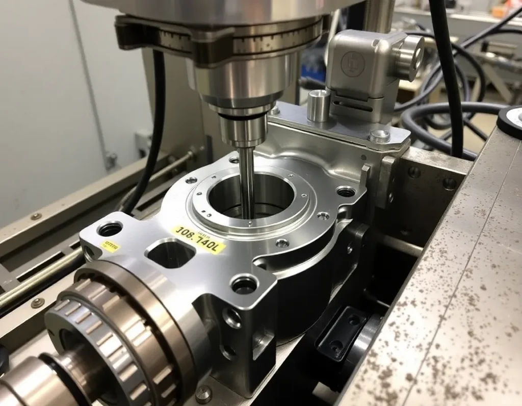
O que é uma Carcaça de Atuador? Fundamentos de Função, Design e Material
Uma carcaça de atuador é o invólucro estrutural que contém e suporta os componentes centrais de um atuador. Pense nela como o bloco do motor de um sistema de movimento. Sua função principal é multifacetada: deve fornecer uma estrutura rígida e estável para suportar forças e torques operacionais, oferecer pontos de montagem precisos para o próprio atuador e suas conexões externas, e frequentemente conter passagens internas para fluidos (em atuadores hidráulicos ou pneumáticos) ou fornecer blindagem para componentes elétricos. O design é inerentemente complexo, integrando recursos como cavidades de furo para pistões ou engrenagens, portas roscadas para linhas de fluido ou sensores, flanges de montagem com padrões de parafusos intrincados e superfícies de vedação que devem ser impecavelmente planas ou cilindricamente verdadeiras.
As considerações de design são determinadas pelo tipo de atuador—linear, rotativo, hidráulico, pneumático ou elétrico. Uma carcaça de cilindro hidráulico, por exemplo, é dominada por um furo interno de alta precisão que deve manter uma vedação perfeita com um pistão. Uma carcaça de atuador de motor elétrico, por outro lado, concentra-se em recursos para assentos de rolamentos, montagem do estator e dissipação de calor. Independentemente do tipo, o design da carcaça é um projeto direto para seus desafios de usinagem, ditando a necessidade de furação profunda, roscamento fino, contorno complexo e integridade superficial excepcional. A escolha do material é a primeira decisão crítica nesta cadeia, preparando o terreno para o processo de usinagem e as propriedades finais do componente.
O Processo de Usinagem da Carcaça do Atuador: Uma Análise Técnica Passo a Passo
A jornada de um blank de matéria-prima até uma carcaça de atuador acabada é uma sinfonia de operações de usinagem coordenadas. Começa com planejamento abrangente e programação CNC, onde o modelo CAD 3D é traduzido em trajetórias de ferramentas de máquina, considerando seleção de ferramentas, velocidades de corte e estratégias de fixação.
1. Preparação do Material e Usinagem de Desbaste
O processo começa com uma peça bruta—uma forja, fundição ou tarugo do metal selecionado. Este blank é primeiro usinado para criar uma geometria inicial uniforme, frequentemente em um torno ou fresadora, para estabelecer datums primários (superfícies de referência). A usinagem de desbaste então segue, onde o grosso do material é removido rapidamente usando cortes agressivos. O objetivo aqui não é precisão, mas eficiência, aproximando a peça de sua forma final enquanto deixa uma pequena quantidade consistente de material—conhecida como sobremetal—para operações de acabamento subsequentes.
2. Criação de Recursos Primários
Com a forma bruta estabelecida, começa a usinagem dos principais recursos funcionais da carcaça. Esta etapa normalmente envolve operações como:
- Mandrilamento: Para cilindros hidráulicos ou pneumáticos, ferramentas de mandrilar de ponto único são usadas para criar o diâmetro interno principal com extrema retidão e circularidade.
- Fresamento de Flanges e Suportes: As fresadoras CNC usinam as faces de montagem, os círculos de furos de parafusos e os contornos externos.
- Perfuração e Rosqueamento: Os furos para portas, sensores, respiros e parafusos de montagem são perfurados e depois roscados com machos de precisão.
3. Semi-acabamento e Alívio de Tensões
Após a remoção primária de metal, a peça pode passar por um tratamento térmico de alívio de tensões. O corte agressivo do desbaste pode induzir tensões internas no material, o que pode causar distorção posteriormente. O aquecimento da peça a uma temperatura controlada alivia essas tensões. As operações de semi-acabamento removem então o mínimo de sobremetal deixado após o desbaste, aproximando a peça ainda mais das suas dimensões finais e preparando-a para as passagens de acabamento de alta precisão.
4. Acabamento e Usinagem de Alta Precisão
Esta é a fase mais crítica. Usando ferramentas afiadas, cortes leves e parâmetros otimizados, os maquinistas alcançam as tolerâncias e acabamentos superficiais finais. As operações aqui incluem mandrilamento fino, brunimento (para acabamento superficial excecional em furos), torneamento de precisão de diâmetros e fresamento de acabamento de superfícies de vedação. Esta etapa impacta diretamente a capacidade de vedação da carcaça, as características de atrito e a vida à fadiga.
5. Operações Secundárias e Inspeção
Uma vez concluída a usinagem, podem ser realizadas operações secundárias. Estas incluem rebarbação (remoção de arestas vivas), lavagem, aplicação de ensaios não destrutivos (como inspeção por líquidos penetrantes para deteção de fissuras) e potencialmente tratamentos superficiais como anodização (para alumínio) ou galvanoplastia. Crucialmente, a peça é então submetida a uma inspeção completa usando máquinas de medição por coordenadas (CMM), comparadores óticos e perfilómetros de superfície para verificar cada dimensão e tolerância em relação ao desenho de engenharia.
Técnicas-Chave de Usinagem: Fresamento CNC, Torneamento e Operações Multi-Eixo
A usinagem moderna de carcaças de atuadores é dominada pela tecnologia de controlo numérico computorizado (CNC), que proporciona a repetibilidade, complexidade e velocidade exigidas para estes componentes.
Fresamento CNC
O fresamento CNC é o cavalo de batalha para criar geometrias complexas, superfícies planas, cavidades e contornos. Uma ferramenta de corte rotativa move-se ao longo de múltiplos eixos lineares (X, Y, Z) para remover material. Para carcaças, o fresamento de 3 eixos é usado para características mais simples, mas a complexidade frequentemente exige mais. O fresamento de 3+2 eixos, onde a ferramenta de corte pode ser orientada num ângulo fixo, permite usinar múltiplos lados de uma peça numa única configuração, melhorando a precisão e reduzindo o tempo de manuseamento.
Torneamento CNC
Realizado em tornos, o torneamento é essencial para usinar simetrias rotacionais. A peça gira enquanto uma ferramenta de corte estacionária a molda. Esta é a técnica principal para criar os diâmetros externos, faces e furos internos de componentes cilíndricos de carcaças. Ferramentas acionadas em tornos CNC modernos — onde ferramentas de fresamento rotativas estão integradas — permitem que operações de perfuração e fresamento sejam concluídas na mesma configuração, um processo conhecido como usinagem de torneamento-fresamento. Isto é incrivelmente eficiente para peças que combinam características cilíndricas e prismáticas.
Usinagem Multi-Eixo (5 Eixos)
Para as carcaças de atuadores mais complexas com ângulos compostos, cavidades profundas ou superfícies contornadas, a usinagem CNC de 5 eixos é indispensável. A ferramenta de corte pode mover-se linearmente ao longo de três eixos enquanto roda simultaneamente em dois eixos adicionais. Isto permite que a ferramenta se aproxime da peça de praticamente qualquer direção num único movimento contínuo. Os benefícios são profundos: a capacidade de usinar geometrias intricadas de outra forma impossíveis, configurações drasticamente reduzidas, vida útil da ferramenta melhorada devido a ângulos de corte ótimos e acabamento superficial superior. Para uma carcaça com portas anguladas, aletas de arrefecimento esculpidas ou características de montagem não ortogonais, a usinagem de 5 eixos é frequentemente o único método de produção viável.
Material Selection for Actuator Housings: Aluminum, Steel, Stainless Steel, and Composites
The performance envelope of an actuator housing is defined by its material. The selection is a careful balance of strength, weight, corrosion resistance, machinability, and cost.
Ligas de Alumínio (por exemplo, 6061-T6, 7075-T6)
Aluminum is the go-to choice for applications where weight savings are critical, such as in aerospace and robotics. Alloys like 6061-T6 offer an excellent strength-to-weight ratio, good corrosion resistance, and outstanding machinability, allowing for high-speed cutting and complex geometries. 7075-T6 is even stronger, approaching the strength of some steels, but can be slightly more challenging to machine. Aluminum is often anodized for enhanced surface hardness and corrosion protection.
Steel Alloys (e.g., 4140, 4340)
For high-strength, high-load applications in industrial automation and heavy-duty automotive systems, alloy steels are preferred. Grades like 4140 pre-hardened steel provide excellent toughness and fatigue strength, capable of withstanding significant shock and dynamic loads. While heavier than aluminum, steel offers superior durability in harsh environments. Machining steel requires more power and slower speeds than aluminum, and parts are often heat-treated (quenched and tempered) after machining to achieve their final mechanical properties.
Aço Inoxidável (por exemplo, 304, 316, 17-4 PH)
When corrosion resistance is paramount—in marine environments, chemical processing, or food and beverage automation—stainless steel is selected. Austenitic grades like 304 and 316 offer excellent corrosion resistance but are relatively soft and can be gummy during machining, requiring specialized tools and techniques. Precipitation-hardening grades like 17-4 PH offer a unique combination: they can be machined in a softer state and then heat-treated to achieve high strength while retaining good corrosion resistance, making them ideal for critical aerospace and defense housings.
Composites and Advanced Materials
In cutting-edge applications, particularly where extreme weight reduction or specific thermal/electrical properties are needed, composites like carbon fiber reinforced polymers (CFRP) are emerging. While not typically “machined” in the traditional metal-cutting sense, they are precision-milled and drilled using diamond-coated tools. Their use in actuator housings is currently specialized but growing, especially in high-performance sectors where every gram counts. The choice of material ultimately dictates the entire usinagem de carcaça de atuador strategy, from tooling and coolant to speeds, feeds, and post-processing requirements.
Tolerances, Surface Finishes, and Geometric Dimensioning (GD&T) for Optimal Performance
The precision of usinagem de carcaça de atuador is quantified and controlled through a strict regime of dimensional tolerances, surface finish specifications, and geometric dimensioning and tolerancing (GD&T). These are not mere numbers on a drawing; they are the engineering language that guarantees the housing will perform its sealing, alignment, and load-bearing functions under real-world conditions.
Tolerances define the permissible limit of variation in a physical dimension. For a bore that must accept a bearing, a tolerance might be specified as ±0.01mm or even tighter. Loose tolerances can lead to play, vibration, and premature wear, while excessively tight tolerances can make manufacturing prohibitively expensive and slow. The key is specifying tolerances that are “fit for function.” Critical sealing surfaces, bearing seats, and mounting interfaces demand the tightest tolerances, often in the range of a few microns, while non-critical external features may have more relaxed specifications to control cost.
Surface finish, measured in microns (µm) or microinches (µ-in), is equally critical. A rough surface on a sealing face will leak; a rough bore will abrade a moving piston rod. Finishes like 0.8 µm Ra (32 µ-in) are common for dynamic seals. Achieving these finishes often requires a multi-stage process: initial machining leaves a rougher surface, which is then refined through precision boring, grinding, or honing. The chosen finish directly impacts friction, corrosion resistance, and fatigue life.
Geometric Dimensioning and Tolerancing (GD&T) is the sophisticated system that moves beyond simple +/- tolerances on dimensions. It controls the form, orientation, location, and runout of features. For an actuator housing, GD&T is indispensable. Flatness tolerances ensure a mounting face sits flush without distortion. Perpendicularity controls ensure ports are square to the sealing surface. True position tolerances define a virtual zone within which the axis of a bore must lie, ensuring perfect alignment of internal components. Concentricity and runout tolerances guarantee that rotating or reciprocating parts move smoothly without binding. By using GD&T, engineers communicate the design intent clearly, ensuring the manufactured housing has the correct geometry, not just the correct dimensions, for flawless assembly and operation.
Quality Control and Inspection: Ensuring Precision and Reliability in Every Housing
Adherence to the stringent specifications outlined in the design phase is verified through a rigorous quality control and inspection protocol. This process transforms a machined block of metal into a certified, reliable actuator housing ready for duty.
Inspection begins at the receiving stage with material certification review. First Article Inspection (FAI) is a critical milestone, where a fully documented inspection of the first part off the production line is conducted against all drawing requirements. This validates that the machining process, tooling, and programming are capable of producing a conforming part. Once production is approved, in-process inspections are conducted at key stages. Operators use calibrated hand tools like micrometers, calipers, and dial indicators to check critical dimensions and features during machining, allowing for immediate corrections and preventing the production of non-conforming parts.
For the most critical features and to verify GD&T, advanced metrology equipment is employed. Coordinate Measuring Machines (CMM) use a tactile probe or laser to collect precise point data from the housing’s surface. This data is compared to the CAD model, generating a detailed report on dimensional accuracy, geometric tolerances, and form. Optical comparators and vision measuring systems provide fast, accurate 2D measurements of profiles and hole patterns. Surface roughness testers, using a diamond-tipped stylus, quantitatively measure the Ra (average roughness) and other finish parameters to ensure sealing surfaces meet spec.
Beyond dimensional checks, non-destructive testing (NDT) methods are often required, especially for high-integrity applications. Dye penetrant inspection can reveal surface-breaking cracks or porosity. For critical aerospace or defense housings, more advanced techniques like X-ray or CT scanning might be used to detect internal flaws invisible to the eye. The final step is often a functional test, such as a pressure or leak test, where the housing is assembled with plugs and subjected to air or fluid pressure to verify its integrity as a sealed vessel. This multi-layered inspection approach, from raw material to finished part, creates a verifiable chain of quality that ensures every actuator housing meets its performance mandate.
Applications Across Industries: Aerospace, Automotive, Robotics, and Industrial Automation
The demand for precision-machined actuator housings spans virtually every sector of modern engineering, each with its unique set of challenges and performance requirements.
Aeroespacial e Defesa
This sector represents the pinnacle of performance and reliability demands. Actuator housings here control flight surfaces (ailerons, rudders), landing gear, thrust vectoring, and weapon systems. Materials are high-strength, often titanium or precipitation-hardening stainless steel. Tolerances are extremely tight, and every part undergoes exhaustive inspection and traceability protocols. Weight is a primary driver, leading to complex, thin-walled designs that push multi-axis machining to its limits. Failure is not an option, making the precision and quality of the housing machining process absolutely critical.
Automotivo
In the automotive industry, actuator housings are found in turbocharger wastegates, electronic throttle bodies, advanced braking systems (ESP/ABS), and increasingly in electric vehicle battery cooling and powertrain management. The focus is on high-volume production, cost-effectiveness, and robust performance under harsh environmental conditions (heat, vibration, contaminants). Aluminum alloys are prevalent for weight savings. Processes are highly automated, with a strong emphasis on statistical process control (SPC) to maintain consistency across hundreds of thousands of parts.
Robotics and Collaborative Robots (Cobots)
Robotics demands actuators that are powerful, compact, and incredibly precise. The housings for robotic joint actuators or grippers must be lightweight to improve payload and efficiency, yet stiff enough to maintain accuracy under load. Designs are often highly integrated, with the housing also serving as a structural frame component. Surface finishes for sealing are critical to keep out dust and debris. The trend towards collaborative robots places additional emphasis on sleek, safe designs with no sharp edges, influencing the final machining and finishing steps.
Industrial Automation and Machinery
This is the broadest category, encompassing housings for pneumatic and hydraulic cylinders, valve actuators, linear guides, and motor drives in factory equipment, packaging machines, and process control systems. Durability and longevity are key. Housings are often made from robust materials like carbon steel or cast iron for larger equipment. The machining must ensure perfect alignment for piston rods and shafts to prevent side-loading and seal wear. Port threads must be clean and precise to prevent leaks in hydraulic systems that operate at thousands of psi.
Resumo dos Pontos Principais
Precision actuator housing machining is a foundational manufacturing discipline that enables motion control across the technological landscape. The process begins with a deep understanding of the housing’s function: to protect, align, and facilitate the operation of internal mechanisms under load. Material selection—from lightweight aluminum and strong steels to corrosion-resistant stainless grades—directly dictates the machining approach and the component’s final properties.
The machining process itself is a symphony of advanced techniques, primarily using CNC milling, turning, and multi-axis machining centers to sculpt complex geometries from solid stock. Achieving the required performance hinges on specifying and holding tight dimensional tolerances, exacting surface finishes for sealing and wear, and comprehensive geometric controls through GD&T. This precision is not assumed; it is guaranteed through a multi-stage quality control regime employing tools from hand gauges to CMMs and NDT methods.
Ultimately, the value of this precise manufacturing is realized in its applications. From the extreme environments of aerospace to the high-volume demands of automotive, the dynamic world of robotics, and the rugged realm of industrial automation, a well-machined actuator housing is a silent enabler of reliability, efficiency, and innovation. It is a component where engineering design and manufacturing excellence converge to create motion.
Perguntas Frequentes (FAQ)
What are the most common mistakes in actuator housing machining?
Common pitfalls include inadequate workholding, leading to vibration and poor surface finish; incorrect tool selection or worn tools causing dimensional inaccuracy; improper sequencing of operations that compromises stability; and neglecting thermal management, where heat from machining can warp the part, especially in thin-walled designs. A lack of in-process inspection can allow a batch of parts to be machined out of tolerance before the error is caught.
How does multi-axis machining benefit actuator housing production?
Multi-axis (5-axis) machining allows complex geometries to be produced in a single setup. This is crucial for housings with ports, bosses, or mounting features on multiple planes. It eliminates the errors that accumulate from repositioning the part between setups, improves accuracy on compound angles, and enables the machining of deeper, more intricate internal features with shorter, more rigid tools, resulting in better surface finishes and tighter tolerances.
Can you machine an actuator housing from a casting or forging?
Yes, and this is common for high-volume or very large housings. A near-net-shape casting or forging provides the basic form, which is then precision machined only on the critical sealing, bearing, and mounting surfaces. This approach significantly reduces raw material waste and machining time compared to starting from a solid block. The machining process must account for potential variation in the casting’s skin and internal structure.
What is the role of post-machining treatments?
Post-machining treatments are essential for enhancing performance. They include heat treatment (to increase strength or relieve stresses), anodizing or plating (for corrosion resistance and wear resistance), and painting or powder coating (for environmental protection and aesthetics). For sealing surfaces, specific finishes like grinding or honing are post-machining operations that achieve the required smoothness. These steps are integral to the final part specification.
How do I choose between aluminum and steel for my housing?
The choice boils down to a trade-off between strength, weight, corrosion resistance, and cost. Aluminum (e.g., 6061-T6) is the go-to for excellent strength-to-weight ratio, good machinability, and natural corrosion resistance—ideal for aerospace, robotics, and applications where weight matters. Steel (e.g., 4140) is chosen for higher strength, stiffness, and durability under extreme loads or wear, common in heavy industrial and hydraulic applications. Stainless steel (e.g., 316) is specified when corrosion resistance is the paramount concern.