
CNC machining standards are not paperwork added after the design is finished. They are the shared language that tells a designer, estimator, programmer, machinist, and inspector what the part must be and how the result should be accepted. A drawing can look detailed and still leave critical questions unanswered if it does not identify the governing dimensioning system, material condition, surface requirements, revision, or inspection expectation.
The Standard Is a Shared Manufacturing Language

| Standard layer | What it communicates | Typical consequence of leaving it unclear |
|---|---|---|
| Drawing and product definition | How dimensions, symbols, views, revisions, and notes are interpreted | The supplier and buyer read the same drawing differently |
| Dimensioning and tolerancing | Size, form, orientation, location, datum, and fit intent | A part passes a size check but fails assembly or inspection |
| Material and finishing | Grade, temper, hardness, coating, roughness, color, and masking | A substitute or post-process condition changes performance or fit |
| Quality and acceptance | Inspection method, report, sampling, traceability, and release evidence | The parties disagree about what “accepted” means |
For a general introduction to how a controlled requirement becomes a machined component, see the site’s CNC machining overview. A standard is useful only when it changes how people interpret, make, or verify the part.
Which Standards Belong in a CNC RFQ?
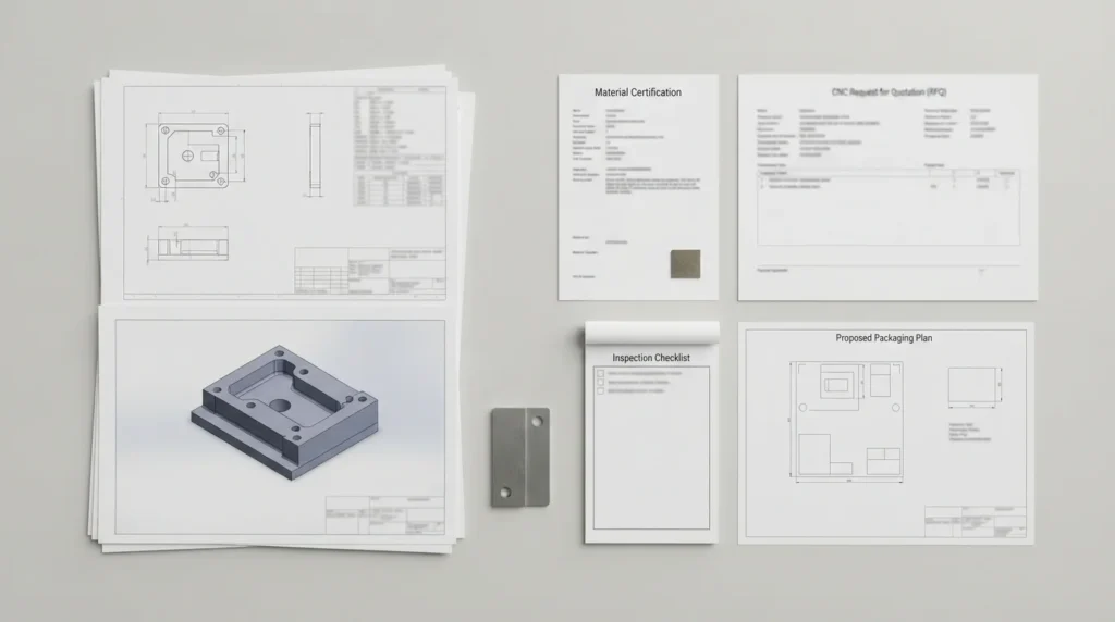
- Dimensioning and tolerancing system, including the edition or revision that governs the drawing.
- General tolerance note and any special rules for angular dimensions, radii, chamfers, or unspecific features.
- Material designation, grade, temper, hardness, reinforcement, grain direction, or certificate requirement.
- Surface roughness, cosmetic zones, coating or plating, anodizing, passivation, polishing, marking, and masking.
- Thread form, size, class or fit requirement, depth, plug-gauge expectation, and whether the thread is through or blind.
- Inspection method, first-article or sampling expectation, dimensional report, traceability, and nonconformance process.
- Revision status, controlled file name, units, and a clear statement about whether the drawing or model governs if they conflict.
Not every part needs a long compliance list. The purpose is to expose requirements that affect quoting, programming, process selection, finishing, inspection, and release. Adding a standard that nobody can interpret or verify does not improve quality.
A Drawing Package Is More Than a 3D Model

Keep model, drawing, and revision aligned
Before sending an RFQ, check that the model and drawing represent the same revision and units. If a model dimension and a drawing note disagree, state which definition controls. File names should make revision status visible, and obsolete files should not remain in the same package without an explicit “for reference” label.
Make functional requirements visible
Tell the supplier if a surface seals, slides, locates, rotates, transfers heat, or must remain cosmetic. That context helps the engineer distinguish a critical feature from a general feature and select a sensible manufacturing and inspection approach. A drawing with fewer but clearer requirements is often more useful than one covered in unexplained tight callouts.
The controlled drawing and RFQ package remain the source for the specific part requirement; a supplier’s process review should explain how those requirements will be interpreted and verified.
ISO and ASME: Decide Which System Governs
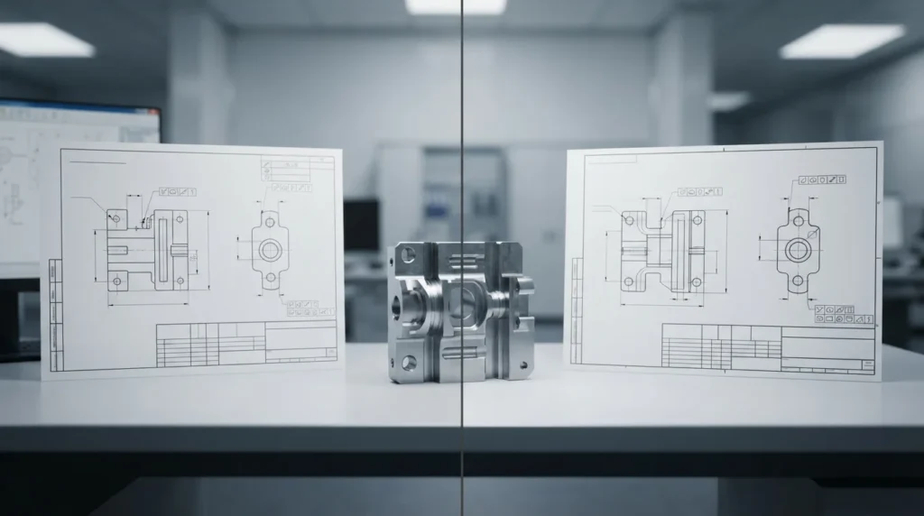
Name the standard and edition
A standard reference without an edition can create uncertainty when requirements or interpretations have changed. Identify the document and revision used by the design authority, then confirm that the supplier and inspector can work to the same reference. If a customer specification adds requirements, it should take precedence only when the package clearly says so.
Do not mix symbols casually
Mixing terminology from different systems without defining how it should be interpreted can create avoidable disputes. Use one coherent framework for GD&T, general tolerances, drawing conventions, and acceptance. When a project must bridge two systems, document the translation during engineering review rather than leaving it to the shop floor.
General Tolerances and Feature Controls
A general tolerance note can simplify a drawing when most dimensions have similar functional importance. It should not replace individual controls for fits, sealing, alignment, controlled motion, or safety-related features. The drawing should make the boundary between general and critical geometry easy to see.
| Requirement | Use a clear callout for | Review question |
|---|---|---|
| Size | Diameters, thicknesses, widths, depths, and fit dimensions | What mating or functional condition does this size control? |
| Location | Hole patterns, slots, pins, interfaces, and reference features | Which datum reference frame represents assembly? |
| Form and orientation | Flatness, perpendicularity, parallelism, roundness, and profile | What failure occurs if this surface or axis is not controlled? |
| Surface condition | Roughness, burrs, edge breaks, coating, and cosmetic zones | Is the requirement measured before or after finishing? |
The relationship between tolerancing and cost is covered in the site’s CNC tolerance guide. Standards should help the supplier apply precision where it matters rather than force every feature into the same risk category.
Material, Finish, Thread, and Inspection Notes
Many quoting and quality problems come from notes that appear simple but are incomplete. Each requirement should tell the supplier what condition is wanted and, when needed, how it will be verified.
- Material: state the grade and condition when strength, hardness, corrosion, weight, or thermal behavior depends on it. If substitutes are allowed, define the approval process.
- Surface finish: state roughness, appearance level, treatment, color, masking, and whether the requirement applies before or after coating.
- Threads: identify the thread system, size, pitch, class or fit intent, depth, relief, and gauge or functional test expectation.
- Edges: define deburring, sharp-edge removal, chamfers, radii, and any edge that must remain controlled for sealing or assembly.
- Inspection: identify critical dimensions, report format, sample size, measuring conditions, traceability, and treatment of nonconforming results.
- Packaging and cleanliness: include protection, contamination limits, protective film, and special cleaning when the application requires it.
For material-related requirements, use the site’s CNC materials library as a navigation point, then place the exact grade and condition on the controlled drawing or purchase specification.
From Standard Callouts to Shop-Floor Acceptance

- Interpret: identify the governing drawing system, revision, units, general notes, and critical characteristics.
- Plan: select setups, datums, tools, material condition, sequence, and finishing steps that support the requirements.
- Verify: decide how each critical dimension, surface, thread, and functional feature will be measured.
- Document: preserve revision, material evidence, inspection results, deviations, and approval records required by the project.
- Release: confirm that the result is accepted against the same definition used for quoting and production.
A quality system is not a substitute for a clear drawing, and a drawing is not a substitute for a controlled inspection method. Both must describe the same product definition. For quality planning context, review the site’s quality information.
CNC Standards Checklist Before Release
Use this short check before sending a drawing package to a CNC supplier:
- Is the drawing or model revision current and clearly identified?
- Are units, decimal conventions, and the governing dimensioning system stated?
- Is the general tolerance rule named, and are critical features individually controlled?
- Are datums, fits, threads, surface roughness, edge conditions, and cosmetic zones understandable?
- Are material grade, temper, hardness, certificate, and permitted substitutes defined?
- Are finishing, coating, masking, cleaning, marking, and post-process dimensions specified?
- Does the inspection requirement identify what must be measured and what evidence is required?
- Does the package explain which document governs if the CAD model and drawing disagree?
- Has the supplier been given enough functional context to flag over-specification or missing requirements?
When the package is complete, submit it through the CNC machining quote workflow so engineering and purchasing can review the same requirements.
CNC Machining Standards FAQs
What standards are commonly used for CNC machining drawings?
Common drawing packages reference a dimensioning and tolerancing system, a general tolerance rule, material and finish specifications, thread requirements, and an inspection or quality standard. The correct references depend on the customer, industry, product risk, and destination market. The package should name the governing standard and edition rather than rely on assumptions.
Do I need both a 3D model and a 2D drawing?
In many drawing-based CNC projects, the model communicates geometry while the drawing or annotated product definition communicates requirements. Providing both reduces ambiguity about datums, tolerances, material, finish, revision, and inspection. If the model is the controlling definition, state that explicitly and include the required product-manufacturing information.
Can ISO and ASME drawing standards be mixed?
A project may need to bridge systems, but symbols and default rules should not be mixed casually. Identify which system governs each requirement and document any approved translation. The supplier and inspector should be able to apply one coherent interpretation to the finished part.
What should a material note include?
Include the material family and exact grade or condition when it affects performance, machining, finishing, certification, or traceability. Add hardness, reinforcement, heat treatment, certificate, or substitute-approval requirements when applicable. The drawing should not leave a critical material decision to an informal message.
How do standards affect CNC machining cost?
Standards affect cost when they require tighter controls, special materials, additional finishing, documented inspection, traceability, or specific testing. Clear requirements can also reduce cost by preventing unnecessary precision and quotation uncertainty. The important point is to specify the level of control that the part actually needs.