Define the part within the reducer assembly
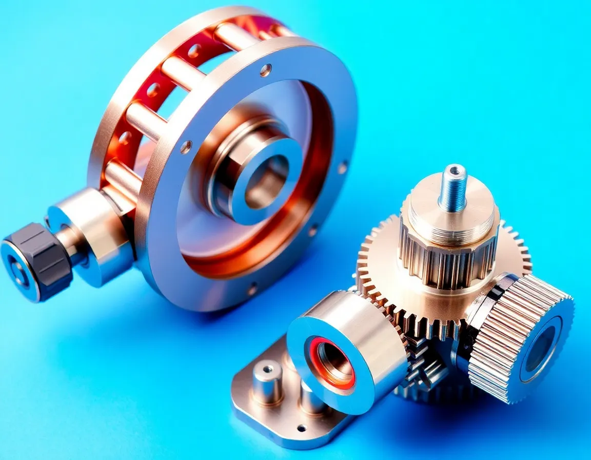
Harmonic drive components may include several parts with different functions and interface requirements. A machining request should identify the specific component in the assembly and provide the drawing revision that controls its dimensions. The machined part is one element of a larger design; performance of the drive cannot be inferred from the component alone.
Make alignment and mounting features clear
Show the datums used to locate the part and dimension interfaces that mate with neighboring components. Depending on the design, this can include mounting patterns, bearing seats, bores, shoulders or shaft-related geometry. Mark which dimensions affect alignment and fit. Do not apply an unverified general tolerance to critical features.
Provide material and finish requirements
Specify material grade and condition, plus any finish or treatment required by the design. Note surfaces that contact other parts or require a defined appearance. Material substitution and process changes should be approved by the design owner.
Choose a manufacturing route from the geometry
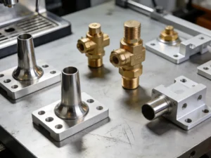
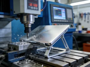
Prismatic housings and plates may call for milling; rotational features may call for turning; some parts need a combination. The route is reviewed against tool access, setups and inspection requirements. For adjacent robotics components, see our Seite zur Bearbeitung von Robotergelenken und die CNC-Fräsen und CNC-Drehen process pages.
Prepare files for a quotation
Send the 2D drawing, 3D model, quantity, material specification, critical dimensions, finish and inspection needs. Include assembly context where it clarifies the interfaces. The team can review the part scope and raise questions before confirming the quotation.