
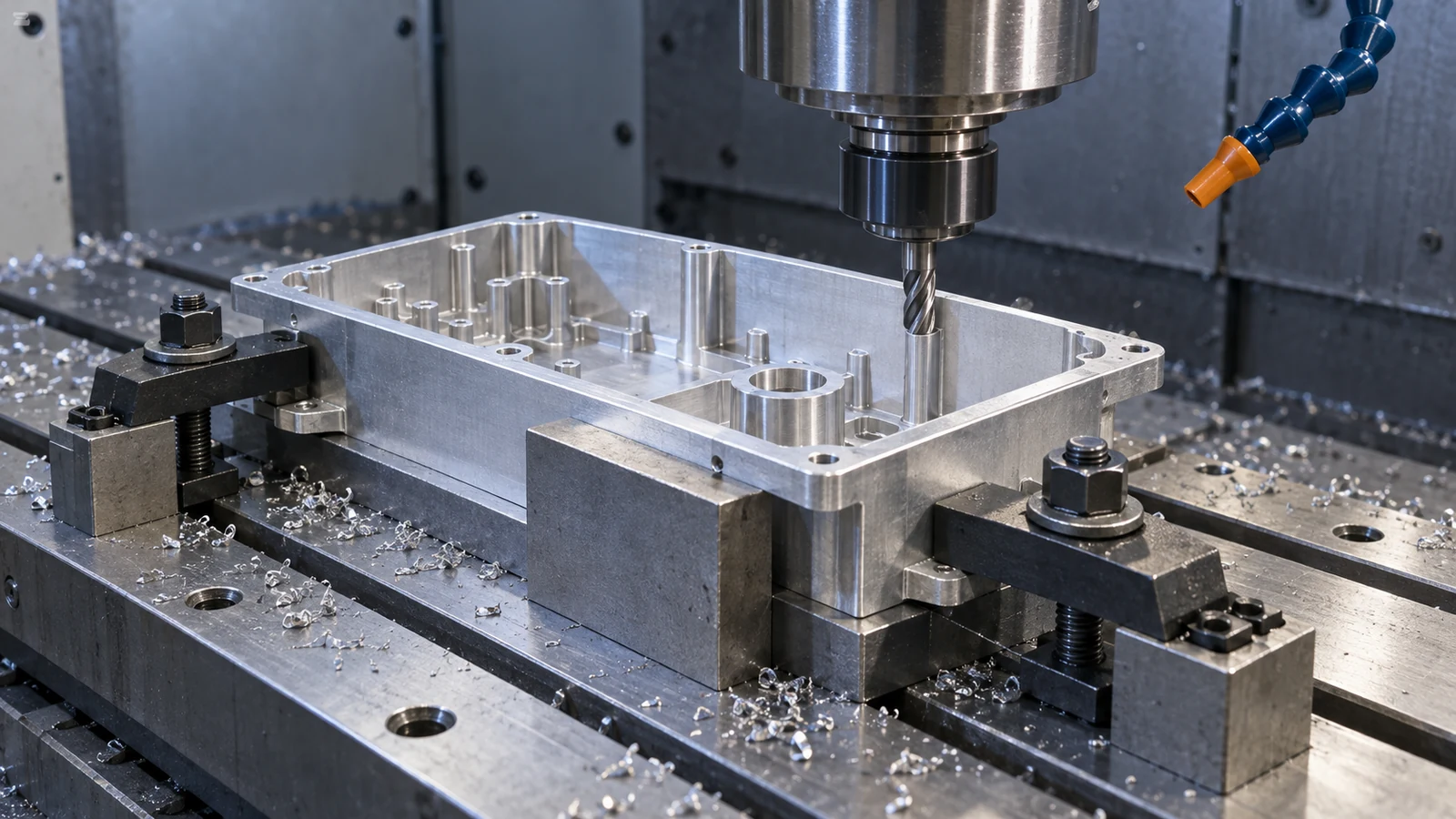
A thin wall can measure correctly while it is clamped and still leave the machine bowed, tapered, or out of position. The cut may be accurate relative to a distorted workpiece. Before changing a finishing pass, separate three possible causes: clamp-induced bending, cutting-force deflection, and residual-stress movement after stock removal. Each calls for a different response.
This guide focuses on thin-wall milling workholding: where to locate and support a flexible feature, how to sequence stock removal without sacrificing access, and when to inspect the part in its free state. It is a narrower decision than the full CNC milling process, which covers the complete route from feature planning to inspection.
The free-state result is the real result
Imagine an aluminum housing held against a solid fixture face. The top edge is milled to the drawing dimension. An in-machine probe or caliper sees an acceptable result, but the housing springs away from the locator when the clamps open. The discrepancy does not prove that the cutter moved to the wrong coordinate. It may show that the fixture changed the shape being cut.
The first question is therefore not “How hard should we clamp?” It is “Which geometry is the drawing asking us to control, and in what state will the customer assemble or inspect it?” Some parts are functionally restrained in an assembly; others must meet dimensions freely supported. That distinction belongs in the drawing and inspection agreement. A fixture should locate the part predictably, not silently redefine the part’s acceptance condition.
Wall height alone is not enough to predict risk. Thickness, unsupported span, material temper, pocket geometry, stock condition, and the direction of the finishing cut all change stiffness. A single universal wall-thickness rule would conceal these variables. The useful workholding decision starts with the actual feature and the direction in which it can move.
Draw the force path before choosing clamps
Sketch the cutter engagement, the direction of cutting force, the likely bending direction, and the surfaces that resist it. A clamp on a delicate lip may hold the blank securely yet pre-bend the finished feature. A locator on an unfinished cast surface may allow the entire part to shift. A large contact pad can spread load, but it can also trap chips or bridge a surface that is not truly flat.
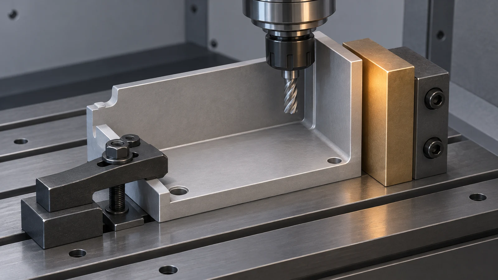
Locate from stable, functionally meaningful surfaces where possible. Support directly behind the region being cut when the geometry allows it; otherwise shorten the unsupported span. Put clamp force into a rigid region of the blank or a temporary stock tab, rather than into the thin wall itself. Support and clamping are related but not identical: support resists cutting displacement, while clamping retains location. Increasing clamp force is not a substitute for a missing reaction surface.
For a housing with several flexible walls, the fixture may need different contact strategies as material disappears. A support that works during roughing might obstruct a final toolpath or falsely restrain the wall during measurement. Plan its removal or relocation as part of the route, and record which operation uses which support.
Support the wall without hiding the toolpath
Soft jaws can distribute contact over a custom profile; local pads can support a rib; a sacrificial frame can keep an open pocket stiff; and a temporary tab can give the fixture a place to grip. None is inherently best. The choice depends on whether the support can be made repeatable, kept clean, removed without damage, and cleared by the cutter and holder.
| Observed risk | Possible workholding response | Check before committing |
|---|---|---|
| Wall bows under clamp load | Move the clamp to rigid stock; use a wider, conforming contact | Does the wall return after release? |
| Wall vibrates during a finishing pass | Shorten the unsupported span or add a local backing support | Does support block the toolpath or leave marks? |
| Part shifts between setups | Revisit datum location and retention, not only clamp force | Are the locating faces stable and chip-free? |
| Part changes shape only after bulk removal | Review stock balance, intermediate release, and finishing allowance | Is residual stress a more likely cause than the clamp? |
A vacuum plate may suit a broad, accessible face but offers no universal answer for a small housing with side-wall cutting loads. Fillers and temporary supports require a documented removal and cleanliness plan. These are process options, not promises about the equipment or materials available for every order. For thin-wall features, ask the machining team to explain how the support and the final free-state inspection relate.
Keep stiffness until it has done its job
Workholding cannot rescue a sequence that removes all useful support too early. Rough the less critical regions while the blank is still stiff, leave a planned finishing allowance, and avoid creating the thinnest wall before the highest-force cuts are complete. Where practical, alternate material removal around a symmetric part instead of leaving one side heavily stressed while the other is finished.
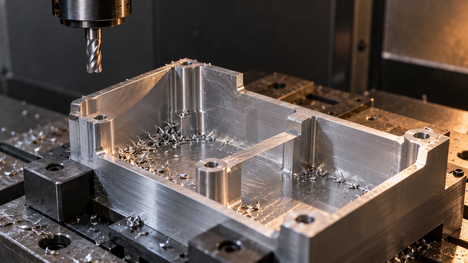
A deliberate route may have a first setup to create reliable datums, roughing with temporary stock intact, an intermediate release or re-clamp to reveal movement, and a low-force finish after the part has stabilized. This is not a universal four-step recipe: the correct sequence depends on material, part shape, tolerances, access, and production quantity. The key is to state why each setup preserves or removes support.
Thin walls also make tool engagement matter. A light finishing pass can still deflect the wall if the cutter pulls it away from a support. Longer tools and aggressive corner engagement can add vibration. A process review should consider cutter direction, remaining stock, chip evacuation, and the surface to be inspected—not just nominal feed and speed. A general discussion of CNC machining process planning provides the broader context; here the priority is maintaining a meaningful force path until the final shape is established.
A diagnostic map for three different failures
If the part is wrong only after unclamping, suspect imposed shape from the fixture or movement released by machining. If the wall shows chatter or size variation while still held, examine dynamic stiffness, support placement, tool condition, and engagement. If several regions move gradually after heavy stock removal—even with gentle clamping—investigate stock condition and residual stress. A change in one variable should have a predicted effect; otherwise it is trial and error disguised as process control.
- Record the clamped result. Measure the same feature while retained, and document the locating scheme.
- Release and remeasure. Use an agreed free-state support condition. Note the direction and magnitude of movement rather than writing only “warped.”
- Re-seat without cutting. If the part returns to the former reading, the fixture is likely imposing shape. If it does not, examine material removal and datum transfer.
- Change one cause at a time. Compare clamp location, support location, or sequence in a controlled trial; do not change them all and then claim which one fixed the problem.
This is a troubleshooting framework, not a substitute for a validated measurement plan. A thin feature that moves with hand pressure or temperature needs an inspection method and uncertainty appropriate to that behavior.
Inspect the part in the condition that matters
A clamped measurement is useful for process monitoring, but it may not represent the delivered part. Define whether the requirement applies free-state, under a specified restraint, or after assembly. Establish where the part is supported, how it is oriented, and whether deburring, surface treatment, and cooling are complete before final inspection. These conditions can determine whether two competent inspectors obtain the same answer.
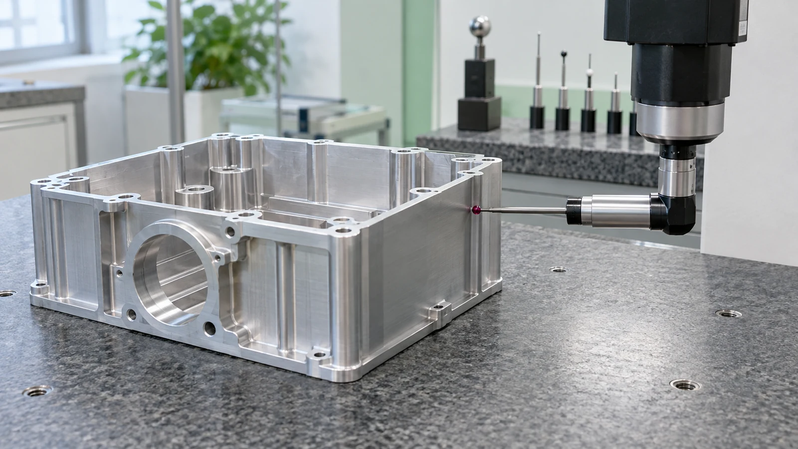
Choose inspection points that reveal the likely deformation mode: along a wall rather than only at its midpoint, across a sealing face rather than only at one corner, or between datum-related features after the fixture is released. The broader quality approach is relevant when discussing documented inspection, but an individual report, machine, or tolerance must still be agreed for the specific order.
When the part fails, report both the clamped and free-state observations. That paired evidence is more actionable than a photograph of a rejected edge or a single out-of-tolerance number.
What to send with a thin-wall RFQ
Send the model and controlled drawing together. Mark the functional faces, assembly datums, critical walls, cosmetic surfaces, and any surfaces that may be used for temporary workholding. State the material grade and stock condition if fixed, the target quantity, post-machining treatments, and which dimensions are assessed in the free state. If a mounting frame or mating part restrains the component in service, include that interface and its load direction.
Ask the supplier to flag features that need sacrificial stock, an alternate datum, or a documented inspection restraint. Do not turn the drawing into a fixture prescription unless a particular method is required by function. The better request is a reviewable process proposal tied to the part’s actual failure risk.
Thin-wall workholding FAQs
Will a lighter clamp always prevent distortion?
No. Too little retention can let the part shift during cutting. The objective is adequate retention with contact and support placed where the part can carry load without being bent.
Can the supplier verify the wall while it stays in the fixture?
Yes, for an in-process check. Whether that reading proves conformance depends on the drawing’s required inspection state. A free-state requirement needs an appropriate released-part measurement.
Is vibration always a fixture problem?
No. Tool reach, cutter condition, engagement, remaining stock, and machine dynamics may be involved. A fixture may contribute by leaving a long unsupported span, but the symptom should be diagnosed rather than assigned to one cause.
Should thin-wall dimensions be tightened to ensure assembly?
Only when a tighter limit controls the relevant function and a suitable inspection condition is defined. Otherwise it may increase rework without addressing the actual interface or deformation mode.