
A facing cut that leaves a small center nub can point to a tool-height problem, but it does not prove one by itself. Nose-radius compensation, tool orientation, insert condition, workpiece movement, and the programmed endpoint can create similar symptoms. A reliable CNC turning setup check isolates those variables before anyone changes an offset or shims a holder.
What center height changes at the cutting edge
On a lathe, the cutting edge must meet the rotating workpiece in the intended relationship to the spindle centerline. A height error changes the effective cutting geometry and clearance at the contact point. The effect becomes especially visible near the center of a faced surface, where the cutting edge approaches the axis and the geometry is no longer the same as it is on a larger diameter.
The direction and severity of the effect depend on insert shape, rake and clearance, holder orientation, tool type, material, and the operation. An external turning tool, a parting blade, a boring bar, and a face-grooving tool do not necessarily use the same reference or correction method. The machine builder’s and tooling supplier’s instructions take precedence over a generic “raise or lower the tool” rule.
For context on how the cutting operation fits into a broader part route, review the site’s CNC turning capability. This article focuses narrowly on center-height setup diagnosis rather than general turning parameters.
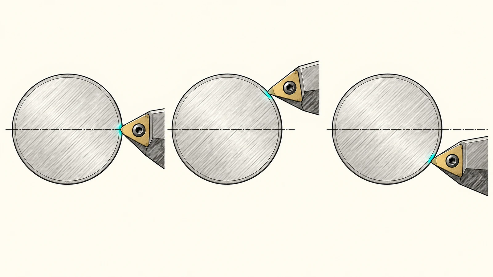
Symptoms that can—and cannot—confirm an error
A center nub or uncut spot at the face center is a useful clue, particularly when the tool is expected to cut across the axis. But the same visible result may occur if the programmed X endpoint stops short, nose-radius compensation is incorrect, the insert edge is chipped, or the setup flexes. A single symptom is not enough to justify a permanent geometry-offset change.
Other clues include a finish that changes as the tool nears the axis, a setup that behaves differently after a holder change, or a cutting edge that appears to rub rather than form a stable chip. These signs still need context. Vibration, feed and speed, built-up edge, chip control, or a worn insert may look like a height error. Compare like-for-like cuts and inspect the actual edge and tool assembly before adjusting the machine.
| Observation | Possible center-height connection | Other checks before correction |
|---|---|---|
| Small nub remains at the face center | Tool may not intersect the spindle axis as intended | X endpoint, nose-radius compensation, tool orientation, insert condition |
| Finish changes close to center | Cutting geometry may be changing near the axis | Feed, speed behavior, chip formation, material condition |
| Only one tool station gives a different result | Holder or insert seating may differ | Clean mounting faces, correct holder, edge height after indexing |
| Multiple tools show a similar offset | A common reference or turret alignment may be involved | Machine-specific setup procedure and qualified calibration checks |
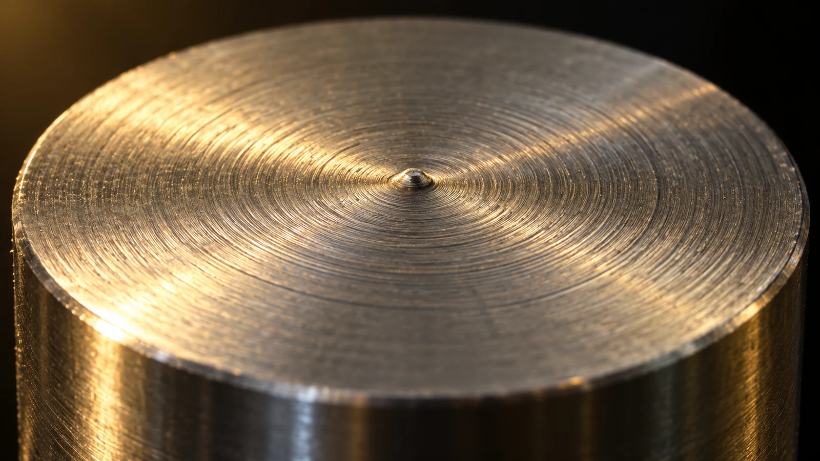
A disciplined center-height setup check
Begin with the part stopped and the machine made safe for setup. Confirm that the holder is intended for the station and operation, its seating faces are clean, and the insert is fully located and clamped as specified. Chips, burrs, a damaged pocket, or a mismatched holder can change the cutting-edge position even when the stored offset has not changed.
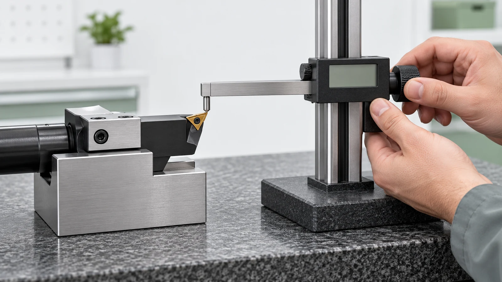
Next verify the tool reference using the machine’s approved method. Some shops use a known centerline reference, a qualified tool-setting system, or a controlled test cut. A facing test can reveal whether a particular tool reaches the axis, but it must be interpreted with the correct tool orientation, insert nose geometry, compensation state, and programmed endpoint. Do not treat a visual center mark as a complete calibration procedure.
For tools that cannot safely make that test, follow the toolmaker or machine-builder procedure for the holder and station. Record the tool type, station, mounting orientation, reference method, and measured correction. A repeatable documented method is more useful than copying a shim thickness from a different lathe.
Why turning, grooving, and boring tools differ
External turning tools may permit a straightforward test cut, but grooving and parting tools have different edge geometries and may be sensitive to side clearance and blade alignment. A height correction that improves one tool can make another tool’s cutting conditions worse. Check the insert’s intended orientation and the holder’s mounting geometry rather than assuming every edge should be corrected the same way.
Boring tools add another constraint: the bar, insert, and bore access interact. A height change can affect clearance inside the hole and may not be adjustable through the same mechanism as an external tool. For driven tools or special stations, use the machine-specific setup instructions; do not infer that a turning-tool method transfers directly.
Correct the setup without guessing at offsets
If the evidence confirms a local tool-height error, use only the correction mechanism approved for that machine and holder—such as a permitted shim, an adjustable holder, or a documented geometry offset. Make a controlled change, rerun the same verification cut, and check the relevant feature. Change one variable at a time so the result remains attributable.
If several stations are consistently high or low, the issue may be common to a turret, tool block, or reference setup rather than each tool independently. Do not compensate every station blindly. A machine-level alignment or calibration concern should be evaluated by qualified personnel using the manufacturer’s procedure. Never bypass safety limits or alter machine parameters based on an unverified symptom.
Keep center-height control repeatable
For repeat orders, record the holder type, insert designation, station, tool orientation, setting method, and any approved correction. Recheck after a crash, holder replacement, insert-pocket damage, turret service, or a change in tool assembly. A compact setup record can prevent a recurring defect from being “fixed” differently on every run.
Inspection should confirm the feature that matters, not just the visual appearance of the face. If the drawing controls a face, diameter, or relationship to another datum, use the specified measurement method and acceptance limits. Center height is a process setup variable; it does not replace drawing-based inspection.
Frequently asked questions
Does a center nub always mean the turning tool is off center?
No. It can result from center-height error, but X travel, nose-radius compensation, tool orientation, edge wear, and workpiece behavior can produce a similar mark.
Can I fix center height by changing the X offset?
Do not use an X offset to mask a height problem without confirming the control’s geometry model and tool setup. First identify which variable is wrong, then follow the machine-specific correction method.
Should all tools on a CNC lathe be exactly the same height?
Each cutting edge must meet its intended reference for the specific holder and operation. Different tool types and mounting arrangements may require different verification procedures.
How often should center height be checked?
Use the shop’s setup and maintenance plan, and recheck after events that can affect seating or alignment, such as holder changes, insert-pocket damage, crashes, or machine service.