
What soft jaws change
Soft jaws are machinable jaw inserts or jaw bodies that can be cut to form a part-specific gripping profile. Compared with generic serrated contacts, a properly matched profile may support a larger area, reduce local marking, or create a more consistent axial stop. They are commonly considered for turned components, round stock, and recurring setups where the contact shape matters.
The benefits depend on how the jaws are cut and how the part is loaded. A close contour can distribute contact, but only if the workpiece seats on the intended surfaces. A pocket cut for one diameter may not locate a different revision correctly. A jaw pair with enough clearance for chips can be more reliable than a perfectly conforming pocket that traps debris. Where dimensional relationships matter, use the part’s drawing datums to define what the jaws should locate—not an arbitrary outer profile.
Soft jaws also do not replace a stable setup. If the workpiece is slender, flexible, or weak near the grip, jaw pressure can still bend or collapse it. For broader alternatives, compare the setup options in CNC workholding methods and the related fixture-design discussion.
Design the contact intentionally
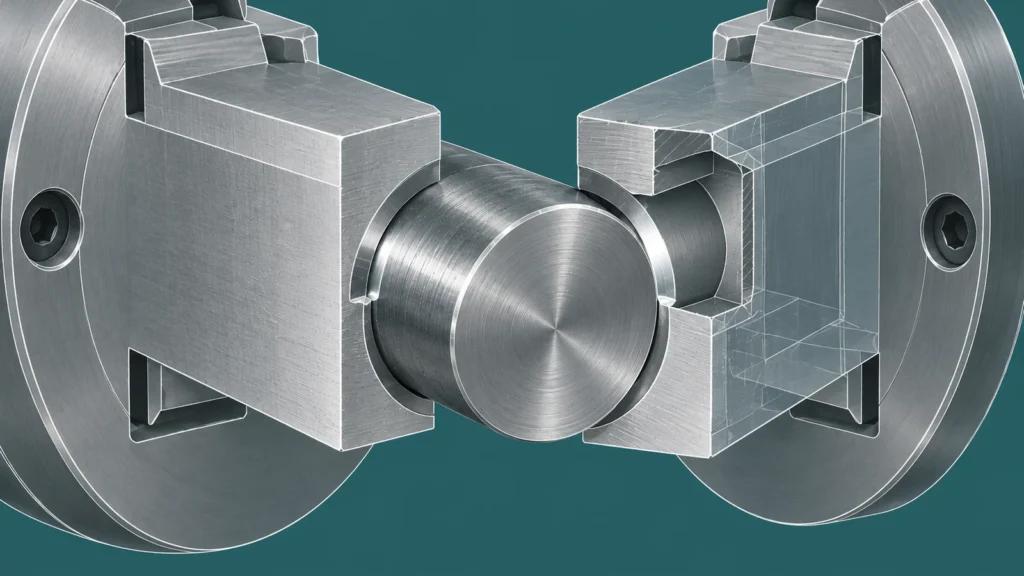 Start by separating location from clamping. A jaw can press the part into a defined stop or shoulder, but relying on friction alone to establish position makes loading sensitive to oil, surface condition, and force variation. Identify the surfaces that locate radially and axially, then define which surfaces only provide holding force. For a turned part, this may mean supporting a cylindrical region while using a face or shoulder to set axial position.
Grip length and contact location should match the operation. Too little engagement can allow the part to tilt or move; excessive engagement can hide a feature that must be machined. Avoid placing pressure on a thin rim, interrupted wall, or finished surface unless the design and process specifically allow it. If the outside diameter will be finished later, preserve sufficient stock for that operation and consider whether the jaws should grip the unfinished or pre-machined condition.
Clearance details matter. Leave a path for chips and coolant, avoid sharp internal corners that interfere with a part radius, and provide enough opening to load the component without scraping the locating surface. Where the jaw pocket is not intended to touch a surface, make that relief deliberate. The goal is a predictable set of contacts—not a cavity that looks close to the part.
Start by separating location from clamping. A jaw can press the part into a defined stop or shoulder, but relying on friction alone to establish position makes loading sensitive to oil, surface condition, and force variation. Identify the surfaces that locate radially and axially, then define which surfaces only provide holding force. For a turned part, this may mean supporting a cylindrical region while using a face or shoulder to set axial position.
Grip length and contact location should match the operation. Too little engagement can allow the part to tilt or move; excessive engagement can hide a feature that must be machined. Avoid placing pressure on a thin rim, interrupted wall, or finished surface unless the design and process specifically allow it. If the outside diameter will be finished later, preserve sufficient stock for that operation and consider whether the jaws should grip the unfinished or pre-machined condition.
Clearance details matter. Leave a path for chips and coolant, avoid sharp internal corners that interfere with a part radius, and provide enough opening to load the component without scraping the locating surface. Where the jaw pocket is not intended to touch a surface, make that relief deliberate. The goal is a predictable set of contacts—not a cavity that looks close to the part.
Machine and install jaws as a system
Jaw machining conditions should represent the working condition as closely as practical. On a chuck, soft jaws are often bored or profiled with a suitable preloading arrangement so the contact geometry reflects the state in which the workpiece will be clamped. The exact method depends on the chuck and jaw system. If jaws are machined without accounting for how they are loaded in use, the contact may shift when the jaws close under operating force.
Before cutting a production part, verify jaw orientation, fastening, seating, and the relationship between the jaw profile and the part datum. Remove burrs and chips from the jaw faces and the part’s locating surfaces. Confirm that all screws and locating features are properly engaged according to the tooling system’s instructions. A jaw set that is swapped left-to-right or installed at a different step position can change concentricity and repeat location.
For a first article or a new jaw revision, check the feature most directly affected by gripping: runout, concentricity, shoulder position, or a critical diameter as applicable. Then release and reload the part to see whether the measurement repeats. This verification is more informative than judging the setup by feel alone. The site’s معلومات الجودة explains why process checks and documented acceptance criteria matter alongside final inspection.
Recognize common failure modes
| العَرَض | Possible workholding cause | What to examine |
|---|---|---|
| Part runout changes after reloading | Inconsistent seating, jaw wear, or a changed jaw position | Contact pattern, jaw step position, chips, and the loading stop |
| Thin section measures differently after release | Excessive or uneven gripping force | Wall stiffness, contact height, grip length, and whether support is distributed |
| Surface marks appear on the component | Small contact area, burrs, embedded chips, or aggressive serrations | Jaw finish, debris, edge condition, and whether a sacrificial contact is appropriate |
| Part seats at inconsistent axial positions | Ambiguous shoulder contact or debris at the stop | Stop design, face cleanliness, chamfer/radius interference, and loading sequence |
| Jaw profile no longer fits after a revision | Part geometry changed without a matching jaw update | Drawing revision, profile allowance, and whether the jaw set is version-controlled |
These symptoms can also have causes outside the jaws, including tool deflection, thermal effects, machine condition, or measurement technique. Diagnose the setup by changing one variable at a time and recording which feature moves. Avoid compensating for a locating problem by adjusting tool offsets before the source is understood.
Make a repeat run repeatable
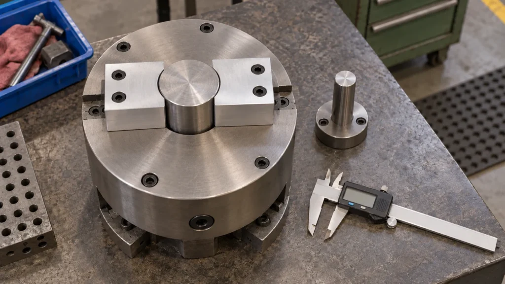 For recurring work, identify the jaw set by part number or revision and keep its intended orientation clear. Record the setup reference, the operation for which the jaws are intended, and any inspection check used to confirm correct loading. This does not require elaborate paperwork for every job; it requires enough information to prevent a future operator from treating visually similar jaw sets as interchangeable.
Inspect jaw contact and locating faces for wear, burrs, and embedded chips at setup. Replace or re-machine jaws when the profile no longer supports the required process, rather than waiting for an unexplained dimensional drift. When a new part revision changes a grip surface, verify that the existing jaw geometry still locates on the intended datum and does not interfere with the new feature.
A practical review asks three questions: does the jaw locate the same datum every time, does it support the part without distorting it, and can the operator confirm correct loading? If any answer is unclear, revise the contact scheme or add a suitable verification step before increasing production volume.
For recurring work, identify the jaw set by part number or revision and keep its intended orientation clear. Record the setup reference, the operation for which the jaws are intended, and any inspection check used to confirm correct loading. This does not require elaborate paperwork for every job; it requires enough information to prevent a future operator from treating visually similar jaw sets as interchangeable.
Inspect jaw contact and locating faces for wear, burrs, and embedded chips at setup. Replace or re-machine jaws when the profile no longer supports the required process, rather than waiting for an unexplained dimensional drift. When a new part revision changes a grip surface, verify that the existing jaw geometry still locates on the intended datum and does not interfere with the new feature.
A practical review asks three questions: does the jaw locate the same datum every time, does it support the part without distorting it, and can the operator confirm correct loading? If any answer is unclear, revise the contact scheme or add a suitable verification step before increasing production volume.
الأسئلة الشائعة
Do soft jaws always improve concentricity?
No. They can provide a part-matched contact profile, but concentricity depends on jaw preparation, chuck condition, loading, force, and inspection. A custom contour alone does not guarantee a result.
Should soft jaws be bored under preload?
Many chuck setups use a suitable preload or compensation method when machining jaws so their working contact reflects the operating condition. Follow the chuck and jaw manufacturer’s method for the specific system.
Can one jaw set be reused for a revised part?
Only after checking that the revised geometry still contacts and locates as intended. A small change to a shoulder, diameter, chamfer, or wall thickness can alter seating or clamping behavior.
What should be checked on a first part?
Measure the features tied to the jaw locating scheme, such as runout, a datum-related diameter, or axial shoulder position. Release and reload the component to assess repeatability, not just the first clamped reading.