
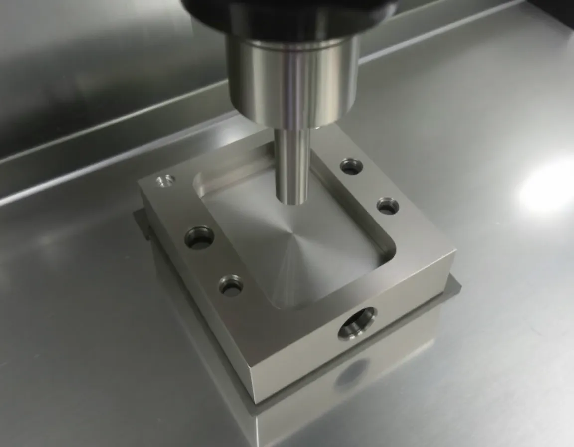
In the world of precision manufacturing, the fixture is the silent hero of the production floor. Whether you are running a high-volume CNC milling operation or a specialized assembly line, the quality of your custom fixture machining often dictates the success or failure of the entire project. A fixture—short for work-holding device—is designed to locate, support, and secure a workpiece during machining or assembly. When done right, it ensures repeatability, reduces cycle times, and guarantees safety. When done wrong, it becomes a bottomless pit of wasted capital.
Custom fixture machining is not just about cutting metal; it is about engineering a solution that integrates seamlessly with your manufacturing process. However, even experienced engineers and machinists fall into common traps that erode profitability. Below, we explore the anatomy of custom fixture machining and the five critical mistakes that could be costing your operation thousands of dollars.
Understanding Custom Fixture Machining
Before diving into the pitfalls, it is essential to understand what custom fixture machining entails. Unlike standard off-the-shelf clamps or vises, custom fixtures are bespoke work-holding tools engineered specifically for a unique part geometry or a specific manufacturing process. They are typically produced through precision CNC machining, utilizing materials ranging from aluminum and mild steel to high-grade tool steels and engineering plastics.
The Role of the Fixture
The primary function of any fixture is to maintain a strict relationship between the tool and the workpiece. In high-precision environments, a deviation of even a few microns can render a part scrap. Custom fixtures address this by providing:
- Locating: Ensuring the part is placed in the exact same position every time.
- Clamping: Holding the part rigidly to withstand cutting forces without deformation.
- Supporting: Preventing vibration and deflection during the machining process.
Why It Matters for Your Bottom Line
The financial impact of fixture design is profound. A well-designed fixture reduces setup time from hours to minutes, allows for multi-part clamping to maximize machine utilization, and ensures that scrap rates remain near zero. Conversely, a poorly machined fixture can cause tool breakage, machine downtime, and catastrophic part failure. The goal of custom fixture machining is to find the sweet spot between rigidity, accessibility, and cost-efficiency.
Mistake #1: Over-Engineering and Over-Complicating the Design
The most common mistake in custom fixture machining is falling in love with complexity. Engineers often design fixtures with the mindset of "just in case." They add extra clamps, over-specify material hardness, and incorporate complex mechanisms for adjustments that are rarely used.
The Cost of Complexity
Every additional feature in a fixture adds to the machining time, material cost, and assembly time. If you design a fixture with five adjustment points when one would suffice, you are not only paying more for the initial build but also increasing the likelihood of operator error during setup. Furthermore, complex fixtures are harder to maintain and clean, which can lead to chips accumulating in critical locating areas, causing misalignment.
The Solution: Design for Simplicity
Effective custom fixture machining focuses on the "Minimum Viable Fixture." This means using the fewest number of components necessary to achieve the required rigidity and repeatability. Ask yourself during the design phase:
- Can this feature be machined into the base plate instead of using a bolt-on stop?
- Is this adjustment knob necessary, or can we use a fixed pin?
- Are we using standard tooling components (like clamps and pins) to reduce machining time?
By simplifying the design, you reduce the machining hours required to produce the fixture, lower the material costs, and create a tool that is more robust and easier for operators to use.
Mistake #2: Ignoring Chip Evacuation and Coolant Flow
In custom fixture machining, the fixture is often viewed purely as a mechanical device. However, it lives in a harsh environment filled with metal chips, coolant, and debris. A failure to account for chip evacuation and fluid dynamics is a massive money-waster.
The Problem: Chip Packing
If your fixture creates "pockets" where chips can accumulate, you are setting your production line up for failure. When chips pack into locating holes or under clamping surfaces, the workpiece will not sit flat. This leads to inconsistent Z-axis heights, chatter, and potential tool breakage. Operators then spend valuable time manually clearing chips, reducing the machine's uptime.
Best Practices for Evacuation
Proper fixture design must include features that allow chips to fall away naturally or be easily washed out by coolant. This requires strategic thinking during the machining of the fixture itself:
- Draft Angles: Avoid vertical walls in chip-prone areas; add draft to allow chips to slide off.
- Through-Holes: Design locating holes as through-holes rather than blind holes so chips can be pushed through.
- Air Blast Provisions: Machine specific ports into the fixture for air blast nozzles to clear critical surfaces before clamping.
- Open Structures: Avoid box-like structures that trap coolant and swarf.
Mistake #3: Underestimating Clamping Forces and Part Distortion
One of the most technically challenging aspects of custom fixture machining is balancing the need for rigidity with the risk of part distortion. This is particularly critical when machining thin-walled components or parts made from soft materials like aluminum.
The Distortion Dilemma
The goal is to hold the part still, but if you clamp it too hard, you deform it. When the machining is finished and the clamps are released, the part "springs back" to its original shape. This results in a part that is out of tolerance. This mistake is often invisible until the final inspection, leading to entire batches being scrapped.
Strategies for Success
To avoid this costly error, the fixture design must account for the material properties of the workpiece. Consider these approaches:
- Distributed Clamping: Instead of one large clamp, use multiple smaller clamps to distribute the force.
- Toggle Clamps: These offer consistent clamping pressure but require careful adjustment.
- Vacuum Fixtures: For thin, flat parts, vacuum chucking provides uniform holding force without mechanical distortion.
- Support Under Clamps: Ensure that the fixture provides support directly beneath the clamping point to prevent bending.
Proper custom fixture machining involves simulating or calculating the clamping force required. If you over-clamp, you waste money on scrap; if you under-clamp, you waste money on broken tools and poor surface finish.
Mistake #4: Neglecting Tool Accessibility and Clearance
A fixture that holds a part perfectly but prevents the cutting tool from reaching the work surface is useless. This is a common oversight in custom fixture machining where the focus is on the "hold" rather than the "machining."
The Collision Risk
If the fixture clamps are too high or the fixture body is too bulky, the CNC machine's spindle or tool holder may collide with the fixture. This can cause catastrophic damage to the machine, the fixture, and the part. Even if a collision doesn't occur, poor accessibility forces the use of longer, less rigid tooling, which increases cycle times and reduces surface quality.
Design for Accessibility
During the design phase of the fixture, a 3D model of the machine spindle and tool holder should be overlaid onto the fixture design to check for clearance. Key considerations include:
- Low Profile Clamps: Use low-profile edge clamps or swing clamps that stay below the cutting plane.
- Clearance for Tool Paths: Ensure the fixture does not interfere with the lead-in and lead-out moves of the tool path.
- Multi-Axis Considerations: If using a 4th or 5th axis, ensure the fixture allows for rotation without hitting the machine's trunnion or table.
Mistake #5: Skipping the Validation and Trial Run
The final and perhaps most expensive mistake is assuming that because the fixture was machined to the correct dimensions, it will work perfectly in production. Custom fixture machining is a precise science, but the real world introduces variables that CAD models do not capture.
The "Cut it and Ship it" Trap
Many shops machine a fixture, bolt it to the table, and immediately start running production parts. If the fixture has a slight defect—a locating pin is 0.01mm too tight, or a clamp is slightly misaligned—the operator will struggle. This leads to slow setup times, operator frustration, and potential scrapping of the first few parts.
The Importance of Validation
Before the fixture goes to the production floor, it must undergo a rigorous validation process. This involves:
- Dry Runs: Running the CNC program without material to check for clearance and tool reach.
- First Article Inspection (FAI): Machining a test part and measuring it thoroughly to ensure the fixture locates the part correctly.
- Gage Repeatability and Reproducibility (GR&R): Loading and unloading the part multiple times to ensure the fixture provides consistent results.
Investing time in validation saves money in the long run. It is far cheaper to adjust a fixture on the bench than to stop a production line because of a design flaw that was missed during the machining phase.
Conclusion
Custom fixture machining is a critical investment in your manufacturing capability. It bridges the gap between raw material and finished precision parts. However, the difference between a profitable fixture and a money pit lies in the details.
By avoiding the pitfalls of over-engineering, ignoring chip evacuation, underestimating clamping forces, neglecting tool accessibility, and skipping validation, you can ensure that your custom fixtures serve their purpose: to make your operation faster, safer, and more profitable. Remember, a fixture is not just a piece of metal; it is a strategic tool that, when machined correctly, pays for itself through every part you produce.