
A robot tool plate can match its nominal hole pattern and still produce poor end-effector alignment. The critical relationship usually runs through more than the bolts: flange face, pilot or register, locating pins, adapter thickness, and the tool’s own datum surfaces all contribute. Robot tooling plate machining should therefore control the interface chain that sets position, not merely reproduce a rectangular plate with holes.
Start with the coordinate relationship the assembly must preserve. Identify which features locate the plate, which fasteners provide retention, and which dimensions control the tool center point or gripper orientation. Then decide what must be measured on the plate itself and what should be verified after assembly.
Map the Complete Interface Stack
Draw the assembly from the robot flange to the working feature: flange, tool plate, any spacer or adapter, end-effector body, and the final tool or gripper. Record the seating face, register diameter or pilot, dowel locations, bolt pattern, and the datum used to orient the tool. A plate can be accurately made to its own drawing and still fail to align if the drawing references an edge that is not used during assembly.
Consider cumulative stack height and angular error. A small tilt at one interface can move a tool point noticeably when the tool extends away from the flange. This does not mean every dimension needs a tight tolerance. It means the drawing should distinguish the locating surfaces and orientation features from clearance holes, cable cutouts, and nonfunctional edges.
If a plate connects a standard robot interface to a custom pattern, identify both interface standards or provide controlled drawings. Do not assume that nominally similar bolt circles are interchangeable; pilot size, register depth, thread form, and face details may differ by robot model or tool family.
Separate Locating from Fastening
Bolts clamp the plate, but clearance holes alone do not necessarily establish a repeatable position. Depending on design and assembly sequence, a close-fitting pilot, dowel pins, a shoulder, or another locating feature may be needed. The location scheme should be deliberate, accessible for inspection, and compatible with how the plate is removed and reinstalled.
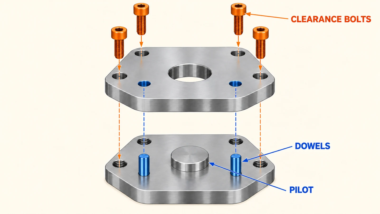
When dowels are used, define their relationship to the primary face and the functional tool axis. Hole position and fit should be selected from the required repeatability and assembly approach rather than copied from a generic drawing. If the plate is expected to be adjustable during setup, show the adjustment range and the method used to lock and verify final position.
Keep the load path in view. Fastener spacing, plate thickness, and support around the pattern influence how the interface behaves when the end effector accelerates or encounters process force. A large cutout may reduce mass but also reduce stiffness around a pilot or bolt group. The design needs enough material where load enters and where locating features are supported.
Check Stiffness and Mass Together
Robot wrists carry moving mass, so weight matters; however, optimizing mass without considering deflection can trade reach performance for compliance. A long cantilevered tool can amplify plate rotation or bending. Review the full assembly mass and center of gravity, then inspect plate sections around the flange and end-effector interface. Ribs or local thickness may be more effective than simply making the whole plate thicker.
Static calculations or simulation can screen designs, but assumptions about fastener preload, contact, and boundary conditions should match the actual assembly. For a prototype, measurements under representative orientation or load can expose compliance that a flat inspection setup will not show. Repeatability and stiffness are related but different: a plate can return consistently while still flexing under load.
Clearance also matters. Slots for wiring, pneumatic passages, and sensor brackets should not interrupt critical lands or make a thin section too flexible. Route cables and hoses so their forces do not pull the tool into a different orientation as the wrist moves.
Machine Holes, Pilots, and Faces from Useful Datums
The primary seating face, locating pilot, and critical hole pattern should be planned as a related feature set. When geometry and machine access permit, completing related features from a stable setup can reduce datum-transfer risk. If multiple setups are required, reference the same functional datum scheme and consider how the workholding establishes it again.
Large plates can move when material is removed, particularly when the design has asymmetric pockets or thin webs. A process plan may use staged roughing, support the plate adequately, and finish critical interfaces after the part is stable. The exact approach depends on stock condition, dimensions, tolerance, and quantity; a universal machining sequence should not be assumed.
For multi-face features or angled interfaces, review whether 3-4 axis milling ou fresamento de 5 eixos better matches the access and datum requirements. The process choice should follow the geometry and inspection plan, not a preference for a machine label.
Select Plate Material for the Load Case
Aluminum is often considered when low moving mass and machinability matter, but grade, temper, section geometry, and surface treatment affect the result. A steel plate may be relevant where a compact, highly loaded interface or wear condition makes its properties useful, though added mass can affect the robot payload and dynamics. Choose material using the actual load, envelope, environment, and assembly constraints.
Do not treat material substitution as a simple density comparison. Stiffness, thread engagement, corrosion exposure, contact behavior, and finishing requirements all affect the design. If anodizing or another coating is specified, identify surfaces that must remain bare or retain a controlled fit. Coating build can affect pilots, holes, and seating interfaces.
Verify Alignment After Assembly
Part inspection should measure the seating face, pilot, hole locations, and tool datum relationship from the stated references. Assembly verification then checks whether the robot-to-tool orientation and position meet the application requirement. Depending on the system, this may involve a gauge, coordinate measurement, probing routine, or controlled setup against a master feature.
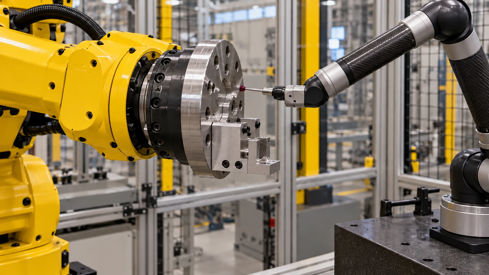
Record whether the check is performed before or after final fastener torque, cable routing, and any adjustment. A plate measured in a relaxed state may behave differently when clamped against a mating face. For troubleshooting, compare the same reference points and assembly conditions rather than mixing a free-state part report with a loaded system measurement.
When alignment drifts after maintenance, inspect contamination on the mating faces, burrs, pin condition, fastener sequence, and cable forces before re-machining the plate. Dirt or a damaged register can create an apparent geometric error without changing the plate’s measured dimensions.
RFQ Details That Prevent a Plate Mismatch
Include the robot model or controlled flange drawing, end-effector interface drawing, material and condition, quantity, finish, and the functional coordinate or datum scheme. Mark which features locate the assembly and which are only for clearance or retention. Provide the expected tool load, reach, and any interface components included in the supply scope.
State whether inspection is required on the plate alone or the assembled interface, and identify the evidence expected. If the design is still changing, mark the revision and distinguish prototype learning features from production-critical interfaces. That keeps machining, assembly, and acceptance aligned.
Tool Plate FAQs
Do bolt holes alone provide repeatable robot tool alignment?
Not necessarily. Clearance holes mainly allow fastener passage; a pilot, dowel, shoulder, or other designed locating feature may be needed depending on the assembly.
Should a tool plate be as light as possible?
It should meet payload and dynamic needs while maintaining adequate stiffness and interface support. Weight reduction that causes deflection or weakens locating features may undermine repeatability.
What should be checked after installation?
Verify the tool datum or center point relative to the robot reference under the specified assembly conditions, including the final fastener state and relevant cable or hose routing.