
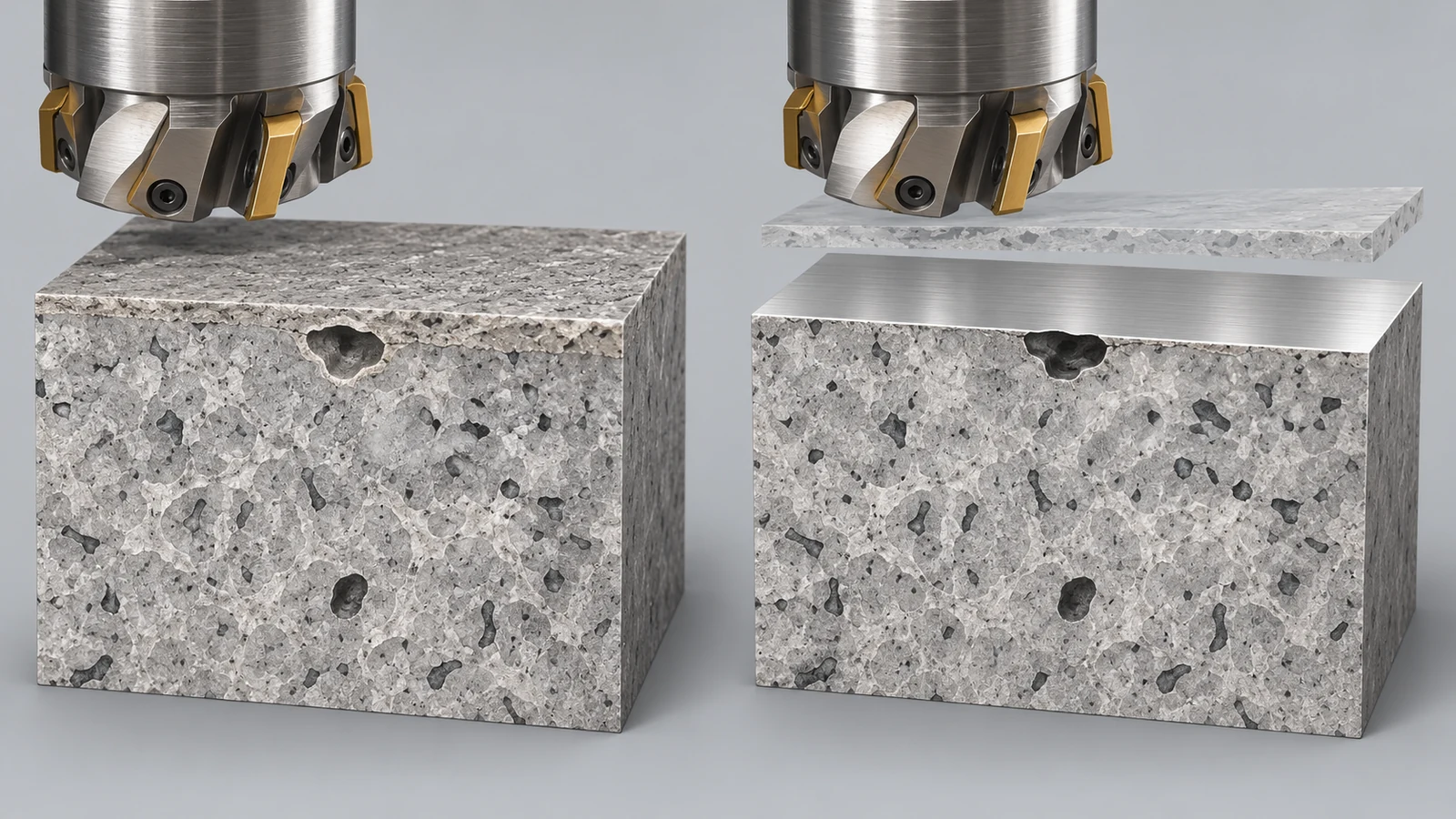
A machined aluminum casting can look sound before the cut and reveal small cavities only after a face, bore, or sealing land is opened. In many cases the machining operation did not create the original void; it removed the material that had hidden it. The response should begin with evidence—where the indication appeared, how deep the cut was, and whether the feature is pressure- or leak-critical—not with an assumption that every pore has the same cause or acceptance rule.
Why porosity appears after machining
Cast aluminum may contain gas-related voids, shrinkage-related porosity, or other discontinuities created during solidification. Their distribution can vary within a part. A machined feature intersects a new plane beneath the as-cast surface, so a previously hidden void can open at the finished face. More material removal can expose additional indications, but a pore’s appearance at the cut surface alone does not prove its exact formation mechanism.
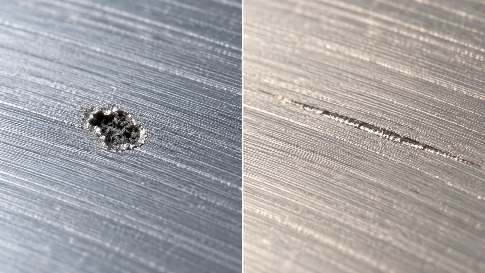
Machining can also create defects that resemble pores. A built-up edge, unstable cutting, a damaged insert, smeared material, chip recutting, or handling damage may leave marks or pullouts. Cleaning can reveal whether a cavity is a persistent feature of the material or loose debris, but a quick visual check cannot identify the full internal extent or determine whether a leak path exists.
When the part is milled, the toolpath, stock allowance, datum, and clamping condition determine which region is exposed. The site’s CNC milling capability provides the process context; the material condition and acceptance criteria must still be established for the particular casting.
Separate a casting pore from a machining mark
Start with a clean, dry surface and inspect under suitable lighting. Note whether the indication is a discrete cavity, a cluster, a drag mark, a raised burr, or a surface tear. Compare the feature with the direction of tool travel and with nearby machined surfaces. A defect that repeats at the same location on multiple castings may point to a casting-related pattern; a mark that follows the toolpath or appears after a tool change warrants a separate process check.
Do not classify a pore as gas porosity or shrinkage solely from a casual photograph. Morphology, section location, casting process records, and appropriate testing may be needed for a defensible root-cause finding. If the part is customer-supplied or cast by another supplier, preserve traceability and report the observation without assigning cause prematurely.
| Observation | Initial question | Evidence to preserve |
|---|---|---|
| Small isolated cavity on a newly machined face | Was material removed from this location, and by how much? | Part ID, face location, machining depth, photos with scale |
| Linear tear or smeared area following the cut | Could edge condition, chip recutting, or unstable cutting contribute? | Tool/insert condition, toolpath direction, process sequence |
| Repeated indications in a similar region across parts | Is there a pattern tied to a casting region or cavity? | Lot and cavity traceability, part orientation, indication map |
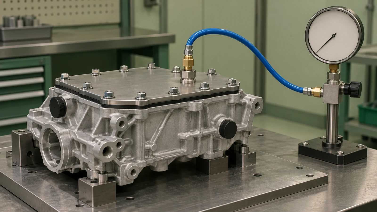
| Leak or pressure-test failure | Does the indication connect through a pressure boundary? | Test method, pressure boundary, leak location, approved disposition |
Record the evidence before reworking the part
Before polishing, blending, sealing, or taking another cut, record the part number and revision, casting lot or trace code, feature location, depth of material removed, and the stage at which the indication appeared. Photograph the area with consistent lighting and a scale reference. If the feature is function-critical, isolate the affected part or lot according to the agreed quality process.
This record helps the casting supplier and machining supplier compare evidence. It also prevents an apparently cosmetic mark from being removed before anyone has decided whether the pressure boundary, wall thickness, or inspection plan is affected. Rework should not erase traceability or conceal the original condition.
Choose inspection based on function
Inspection depends on what the part must do. Visual examination can document exposed surface cavities. A penetrant method may reveal surface-connected discontinuities on a suitable, properly prepared surface, but it does not map all internal porosity. Radiography or computed tomography may help evaluate internal volume and distribution when the geometry, material thickness, and required sensitivity are suitable. A leak test evaluates functional leakage under its specified conditions; it is not interchangeable with a general porosity measurement.
For a sealing face or pressure-containing component, acceptance should be tied to the actual pressure boundary and test requirement. For a non-pressure cosmetic surface, the criteria may be different. Do not infer that one inspection method guarantees another property, and do not invent a universal pore-size limit. The drawing, customer specification, and qualified inspection procedure govern.
Set acceptance and disposition rules
Agree in advance whether exposed porosity is acceptable, rejectable, or subject to engineering review. Define the affected surfaces, any functional tests, the lot scope, and who can authorize rework or concession. If a part fails a leak test, a visible pore may be a clue, but the actual leak path and test result determine the functional failure.
Potential dispositions—such as repair, impregnation, re-machining, concession, or scrap—are application-specific. Each can affect dimensions, cleanliness, coatings, compatibility, and service performance. The supplier should not select a repair solely because it hides a visible cavity. Obtain customer or design-authority approval where required and re-verify the affected function after any approved rework.
Reduce repeat findings on the next lot
Use the location and depth records to determine whether the issue is isolated or recurring. If it repeats, coordinate with the casting source to review the relevant process records and inspection plan. At the machining stage, review whether the drawing defines the cast-versus-machined boundary, minimum wall, stock allowance, datums, and the surfaces that require leak or pressure validation.
Sampling before a full production run can reveal whether machining exposes a recurring condition. For a critical sealing face, agree on the sequence of machining and testing, because a test performed before the final material removal may not evaluate the final pressure boundary. The goal is not to promise defect-free castings; it is to make the risk visible early and align inspection with the component’s function.
Frequently asked questions
Does CNC machining cause porosity in an aluminum casting?
Often, machining exposes voids that were already below the as-cast surface by removing the covering material. Cutting conditions can create other surface defects, so inspect the mark and process evidence before assigning a cause.
Can I identify gas porosity from a surface photo?
A photo can document shape and location, but it is not enough to establish the defect mechanism or internal extent. Root-cause identification may require casting records or qualified testing.
Does a visible pore mean the casting will leak?
Not necessarily. Leakage depends on whether a connected path crosses the pressure boundary and on the specified test conditions. Use the required functional leak test when leak tightness is the acceptance need.
Should the pore simply be filled or sealed?
Only under an approved disposition. A repair may affect dimensions, cleanliness, finishing, or service behavior, so verify the functional requirement after any authorized rework.