
CNC tolerance stack-up analysis for assemblies explains why several individually acceptable parts can still create a tight, loose, misaligned, or nonfunctional assembly. The analysis follows a functional dimension chain from one locating surface to the final interface, then compares worst-case and statistical variation before the drawing is released. It is an assembly-planning exercise, not simply a request for tighter tolerances on every CNC feature.
The Assembly-Level Answer
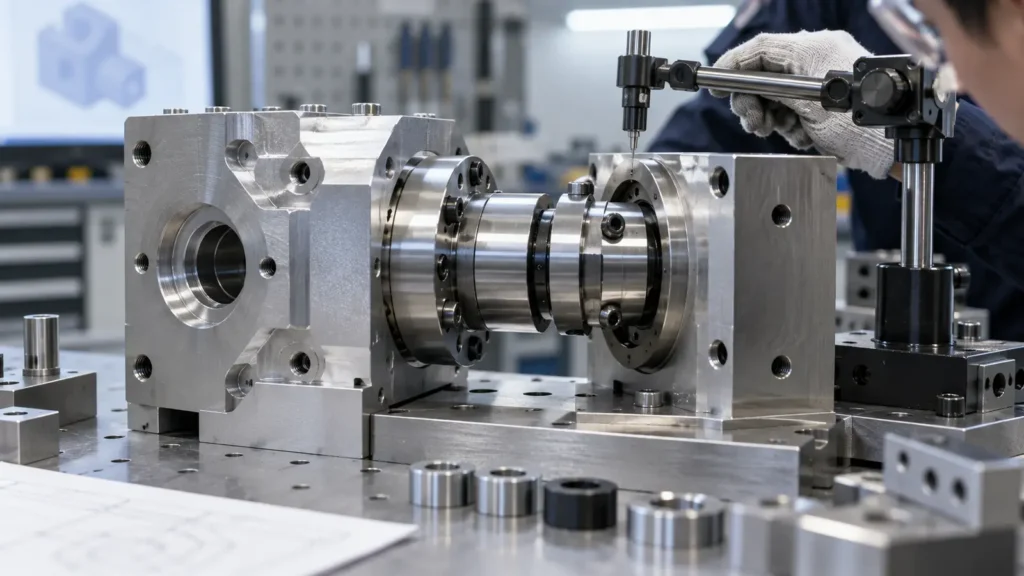
Define the assembly result
A stack-up needs a measurable output. Examples include a minimum clearance for a moving slide, a maximum gap around a cover, a hole-to-pin alignment window, a bearing preload range, or the travel remaining after two stops meet. “The parts must fit” is not specific enough to build a useful chain.
Write the requirement as a limit or range, identify the inspection or functional test, and state the assembly condition. Temperature, lubrication, gasket compression, coating, fastener torque, and the order of assembly can change the result.
Build the dimensional chain
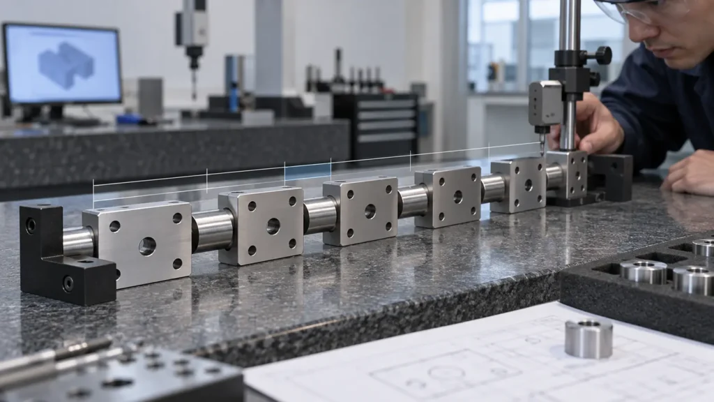
| Contributor | Assembly effect | Review point |
|---|---|---|
| Part thickness | May reduce or increase a clearance | Is the dimension measured from the functional datum? |
| Hole or pin location | Controls alignment and insertion margin | Does orientation belong in the chain too? |
| Spacer or coating | Changes final stack height | Which process state is the controlled state? |
Choose an analysis method

Statistical analysis estimates the distribution of the assembly result from process variation. RSS or Monte Carlo methods can reduce unnecessary tightening, but only if the distributions, centering, independence, sample size, and production controls are realistic. Statistical yield is not a substitute for a hard minimum or maximum when one failure can damage the product.
Include geometric variation
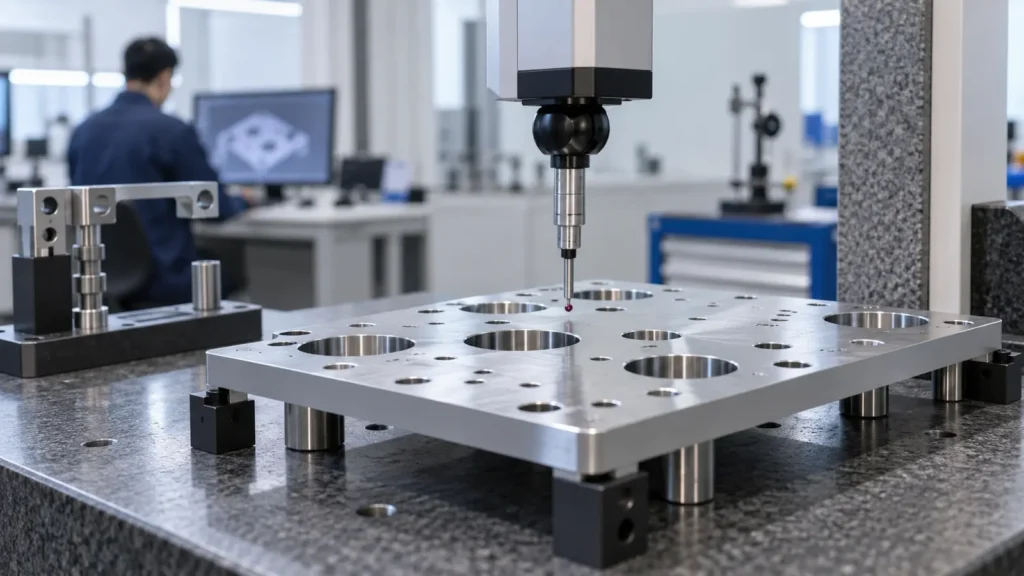
Use the datum reference frame that the assembly actually uses. The site’s CNC machining tolerances guide provides the single-part tolerance context; this analysis extends it to relationships between parts.
Turn the result into drawing action
Do not automatically tighten every contributor. Rank the chain by sensitivity and manufacturing risk. A dominant hole location may need a position control, while a nonfunctional outside edge can keep its general tolerance. A stack-up may also show that changing a datum, adding an adjustment feature, splitting a tolerance, or changing the assembly sequence is more effective than demanding tighter machining.
- Identify the largest contributors to the output range.
- Check whether the drawing controls the correct size, location, orientation, or form characteristic.
- Review whether coating, heat treatment, deburring, and assembly add variation.
- Recalculate after each design change and record the accepted assumptions.
Verify the assembled condition
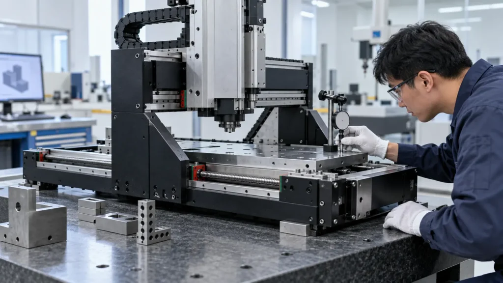
For a complex assembly, align the measurement plan with the supplier’s quality and inspection process. Keep the stack-up assumptions with the revision so future changes to material, finish, or supplier process can be evaluated consistently.
Tolerance stack-up FAQs
When is worst-case analysis necessary?
Use it when the assembly must meet a guaranteed boundary across the specified component limits or when a single failure has unacceptable consequences. It is conservative, but it makes the acceptance condition easy to explain.
Can tighter CNC tolerances solve every stack-up problem?
No. A datum change, feature relocation, adjustment allowance, improved assembly sequence, or control of position and orientation may reduce risk more effectively than tighter size limits.
Should coatings be included?
Yes, when the coating changes a mating size, gap, friction, sealing surface, or locating condition. State the controlled state and include coating variation in the relevant chain.
What is the most common stack-up mistake?
The most common mistake is analyzing nominal linear dimensions while ignoring datum transfer, feature orientation, surface condition, or the actual assembly sequence.