Define the mechanical part, not an unsupported system claim
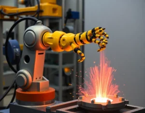
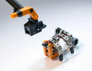
Robotic limb machining here refers to making custom mechanical components shown on a customer drawing, such as links, brackets, mounts or joint-related parts. A machined component does not by itself establish load capacity, movement quality or safety. Those outcomes depend on design, assembly and validation.
Make interfaces easy to review
Provide the assembly context and identify pivot bores, mating faces, fasteners, locating features and critical distances. Use clear datums and note which dimensions control motion or alignment. Add section views where the geometry or internal features are not clear from the model.
Specify material and acceptance needs
State the material grade and condition, quantity, finish and inspection requirements. Mark the surfaces that contact other parts and any critical dimensions that need measurement records. Any material substitution, tolerance or finish change should be reviewed and approved by the design owner.
Choose the machining route from geometry
Links and mounts may involve milling, turning, drilling or a combination depending on shape and access. See our página de mecanizado de articulaciones robóticas for a related component topic, along with Fresado CNC process information.
Submit a drawing-based request
Send the 2D drawing and 3D model, quantity, material, critical interfaces, finish and inspection scope. Identify application-specific acceptance criteria and who is responsible for system validation. The team can review the part for machining and clarify scope before quotation.