
In an era defined by visual communication and data-driven discovery, the clarity of an image or the stability of a sensor can be the difference between success and failure. This foundational stability, upon which cameras, telescopes, lasers, and surveying instruments rely, is not a matter of chance. It is the product of meticulous engineering and manufacturing precision. At the heart of this reliability lies a seemingly simple yet critically complex component: the tripod mount. This specialized interface is the unsung hero, the literal connection point that transfers vibration, supports weight, and maintains alignment. The process of creating these vital components, known as tripod mount machining, is a discipline where advanced manufacturing meets exacting mechanical standards. It transforms raw metal into a flawless, reliable interface, ensuring that whether capturing a once-in-a-lifetime photograph or conducting precise geospatial analysis, the equipment remains steadfastly secure and perfectly oriented.
What is Tripod Mount Machining? Defining the Interface Standard
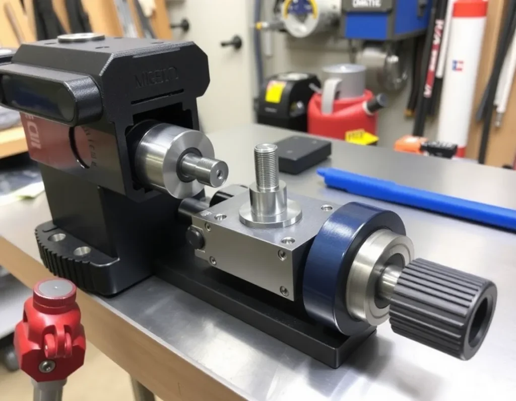
Tripod mount machining is the specialized manufacturing process of creating the standardized threaded sockets, plates, and receptacles that allow equipment to be securely attached to a tripod or other stabilizing platform. It is far more than just drilling a hole; it is the engineering and production of a complete mechanical interface system designed for repeatable attachment, precise alignment, and load-bearing reliability. This process defines the universal language between a device and its support. While commonly associated with consumer photography, the scope of tripod mount machining extends to any field requiring a stable, detachable mount for instrumentation. The machining process must account for thread form, depth, concentricity, and the perpendicularity of the mounting surface to the device’s optical or measurement axis. A poorly machined mount introduces play, misalignment, and instability, directly degrading performance. Therefore, this machining discipline is centered on creating a perfect, standardized interface that becomes functionally invisible—allowing the user to connect equipment with absolute confidence in its rigidity and precision.
The Anatomy of a Tripod Mount: Threads, Plates, and Receptacles
Understanding tripod mount machining requires a dissection of the mount’s core components. Each element plays a distinct role in the system’s overall function and must be machined to exact specifications.
Threads: The Primary Fastening Mechanism
The threaded receptacle is the most fundamental element. The two dominant standards are the 1/4″-20 UNC (Unified National Coarse) and the larger, heavier-duty 3/8″-16 UNC. The “20” and “16” refer to threads per inch. Machining these threads involves creating a clean, precise helical structure with the correct major and minor diameters. The thread’s depth and the receptacle’s wall thickness are critical for strength, especially in materials like aluminum. A cross-threaded or out-of-spec receptacle can fail catastrophically.
Mounting Plates and Quick-Release Systems
For professional and industrial use, a direct thread connection is often too slow. This led to the machining of quick-release systems, which consist of two parts: a plate that attaches to the device and a receptacle on the tripod head. The plate, often machined from steel or aluminum, features a precise dovetail or locking groove and a threaded hole. The mating clamp on the tripod must be machined to match this geometry with zero play. The tolerances here are exceptionally tight, as any slop translates directly to camera or instrument movement.
Receptacle Housings and Reinforcement
The threaded socket or quick-release clamp doesn’t exist in isolation. It is housed within a larger component—be it a camera’s baseplate, a telescope’s tube ring, or a laser housing. Machining involves integrating this receptacle into the host device. This often requires creating a reinforced boss or a threaded insert (a heli-coil or press-in brass insert) to prevent wear and stripping in softer metal housings. The alignment of this receptacle’s axis relative to the device’s functional axis is a paramount consideration during the machining setup.
Core Machining Processes for Tripod Mounts: From CNC to Thread Rolling
The creation of a reliable tripod mount employs a sequence of advanced machining processes, selected based on material, volume, and precision requirements.
CNC Milling: Shaping the Foundation
Computer Numerical Control (CNC) milling is the workhorse for creating the mounting plates, receptacle housings, and complex quick-release mechanisms. A CNC machine uses programmed commands to control cutting tools with extreme precision. It can machine the flat mounting surface, drill the pilot hole for the thread, and cut the intricate profiles of a quick-release dovetail—all in a single setup. This ensures perfect alignment between all features, which is impossible to guarantee if operations are performed on separate machines.
Drilling and Tapping: Creating the Threaded Core
For the threaded socket, the process begins with drilling a pilot hole to a specific diameter. Following this, tapping—the process of cutting internal threads—is performed. This can be done with a manual tap on a drill press for low volumes, but for consistency in production, CNC machines often use rigid tapping, where the spindle’s rotation and vertical feed are perfectly synchronized to produce clean, accurate threads without breaking the tap.
Thread Rolling: A Superior Alternative for Strength
For high-strength applications, thread rolling is often preferred over cutting. This cold-forming process uses hardened dies to displace the material into the thread form, rather than cutting it away. This results in threads with smoother surfaces, work-hardened grains (increasing strength), and no cut fibers that can initiate cracks. Rolled threads are more fatigue-resistant and durable, making them ideal for heavy-duty or frequently used mounts in industrial settings.
Turning and Boring on CNC Lathes
For cylindrical components like threaded inserts or the clamping knobs for quick-release systems, CNC turning is essential. A lathe rotates the workpiece while a stationary cutting tool shapes it. This process is perfect for achieving concentricity and smooth external threads. Boring is used to enlarge and finish an existing hole to a very precise diameter and surface finish, often as a preparatory step for pressing in a threaded insert.
Material Selection for Durability and Performance: Aluminum, Steel, and Composites
The choice of material in tripod mount machining is a critical balance between weight, strength, corrosion resistance, and machinability. The wrong material can lead to rapid thread wear, galling, or mechanical failure.
Aluminum Alloys: The Standard for Lightweight Gear
Aluminum, particularly alloys like 6061-T6, is ubiquitous in consumer photography and electronics. It offers an excellent strength-to-weight ratio, is highly machinable, and resists corrosion. However, aluminum is relatively soft. Repeated threading and unthreading of a steel tripod screw into an aluminum socket can lead to wear and eventual stripping. To combat this, machinists often press a harder brass or stainless steel threaded insert into the aluminum housing, dramatically extending the mount’s service life.
Stainless Steel: For Corrosion Resistance and High Loads
Stainless steel alloys, such as 304 or 316, are chosen for applications where strength, durability, and resistance to harsh environments are paramount. Scientific instruments, marine equipment, and military hardware frequently use stainless steel mounts. While heavier and tougher to machine than aluminum, stainless steel provides exceptional thread durability and will not rust, making it ideal for field use in all conditions.
Carbon Steel and Alloy Steel: Maximum Strength
For the most demanding industrial applications—such as mounting large broadcast lenses, heavy laser cutters, or seismic sensors—high-strength alloy steels like 4140 or 4340 may be used. These materials can be heat-treated to achieve tremendous tensile strength. They are almost always used with a protective plating or coating (like nickel or zinc) to prevent corrosion. The quick-release plates on high-end tripod heads are often machined from these steels for their resistance to deformation and wear.
Advanced Composites and Titanium
In aerospace and high-end performance sectors, materials like titanium and carbon-fiber-reinforced polymers (CFRP) are machined for mounts. Titanium offers a strength-to-weight ratio superior to steel and excellent corrosion resistance but is challenging and expensive to machine. Composites are extremely light and stiff but require specialized machining techniques to prevent delamination and require metallic inserts to be bonded in to provide a durable threading surface.
Tolerances and Precision: Why Micron-Level Accuracy is Non-Negotiable
In tripod mount machining, “close enough” is a recipe for failure. The entire value of the mount lies in its ability to provide a rigid, repeatable connection with zero unwanted movement. This demands adherence to tolerances measured in microns (thousandths of a millimeter).
Consider the thread interface. A 1/4″-20 thread has defined tolerances for its pitch diameter. If the tapped hole is even slightly oversized, the mating screw will have lateral play, causing the equipment to wobble. If it’s undersized, the screw will bind or cross-thread, damaging both components. The perpendicularity of the threaded hole to the mounting surface is equally critical. If this axis is off by even a small angle, tightening the screw will induce a bending moment, pulling the device out of alignment and creating a point of high stress that can lead to failure.
For quick-release systems, the tolerances are even more extreme. The mating dovetail or Arca-Swiss style plate must slide smoothly into the clamp but, when locked, must have no detectable movement. This requires machining the locking groove and the clamp’s jaws to tolerances that ensure a seamless transition from free movement to absolute rigidity. Any imperfection in the surface finish or geometry results in “slop,” which at telephoto focal lengths or high-magnification microscopy renders the equipment unusable.
This precision is achieved through calibrated, high-quality machine tools, rigorous in-process inspection, and skilled machinists who understand the functional outcome of every dimension on the blueprint. The use of Coordinate Measuring Machines (CMM) and optical comparators to verify critical features post-machining is standard practice. In essence, the silent, unwavering stability we expect from a mounted device is purchased directly with micron-level precision in the machining process.
Applications Beyond Photography: Scientific, Industrial, and Military Uses
While the tripod mount is synonymous with cameras, its role as a universal, precision interface for stabilization and attachment is foundational across numerous high-stakes fields. The principles of tripod mount machining are directly applied to create reliable connection points for equipment where failure is not an option. In scientific research, vibration isolation is paramount. Laboratory-grade optical tables and breadboards are often equipped with a grid of precisely machined threaded holes, typically 1/4″-20 or M6, allowing researchers to securely mount lasers, mirrors, sensors, and microscopes. The repeatability and rigidity afforded by these machined mounts ensure that experimental setups are not only stable but also reproducible over time, a critical factor in longitudinal studies. In astronomy, telescope guide scopes, CCD cameras, and filter wheels all utilize standardized or custom tripod-style mounts to maintain perfect optical alignment despite temperature shifts and positional changes.
Industrial applications demand even greater robustness. Machine vision systems used in automated quality control on high-speed production lines rely on machined mounts to position cameras and lighting units with unerring accuracy. Any shift in the camera’s angle could lead to misidentification of defects, costing thousands in scrap or recalls. Similarly, in surveying and LiDAR scanning, the mounting interface between the scanner and its tripod or mobile platform must be machined to withstand environmental harshness while eliminating any play that would distort spatial data. The military and defense sectors push these requirements to the extreme. Equipment such as thermal imagers, rangefinders, and communication devices mounted on vehicles, aircraft, or carried by personnel use specialized, hardened mounts. These are often custom-machined from high-strength alloys with features like quick-release levers, anti-rotation pins, and sealing gaskets to protect against shock, vibration, dust, and moisture. The common thread across all these applications is the non-negotiable need for an interface that transforms separate components into a single, rigid unit, a need met by precision machining.
Design Considerations and Standards: 1/4″-20, 3/8″-16, and Custom Solutions
The design of a tripod mount is a balancing act between universal compatibility, mechanical strength, and application-specific needs. This has led to the establishment of dominant standards alongside a world of custom solutions. The most ubiquitous standard is the 1/4″-20 UNC threaded socket. This simple coarse thread, measuring 1/4 inch in diameter with 20 threads per inch, is the de facto connection for consumer cameras, many video accessories, and a vast array of lightweight scientific gear. Its prevalence makes it a default starting point for design. For heavier payloads, the 3/8″-16 UNC thread is the standard. This larger, stronger thread is commonly found on professional video tripod heads, large format cameras, and heavier industrial equipment. Many professional devices feature a dual-threaded receptacle—a 3/8″-16 socket with a removable 1/4″-20 adapter insert—providing maximum flexibility.
Beyond these imperial threads, the metric M6 (6mm diameter, 1mm pitch) is a widely used European standard, functionally similar to 1/4″-20. For quick-release systems, the Arca-Swiss dovetail has become a quasi-standard, particularly in photography and optics. Its 45-degree dovetail profile and standardized width allow for interoperability between plates and clamps from many manufacturers, though subtle variations in tolerances and groove placement can affect performance. Design considerations extend far beyond the thread or dovetail. Engineers must account for the wall thickness around a threaded receptacle to prevent stripping, the depth of engagement for the screw to ensure load is properly distributed, and the use of reinforcing ribs or backings in plastic or composite housings. For custom solutions, such as a mount for a unique sensor on a drone, design may incorporate anti-vibration bushings, locking levers instead of screws, or electromagnetic coupling for rapid swap-out. The choice of standard or custom design is ultimately dictated by the required load capacity, environmental conditions, need for end-user compatibility, and the precision demanded by the application.
Quality Control and Testing: Ensuring Reliability in Every Mount
The integrity of a machined tripod mount is validated through a rigorous regime of quality control and testing. This process begins with the inspection of raw materials and continues through every stage of production. For threaded receptacles, thread gauges—both Go and No-Go gauges—are essential. The Go gauge must thread in smoothly to full depth, confirming the minimum material condition and proper pitch diameter. The No-Go gauge must not thread in more than a specified number of turns, confirming the maximum material condition and preventing an overtightened, binding connection. For critical components, thread profiling with optical comparators or dedicated thread measurement systems provides a complete analysis of thread form, angle, and pitch.
Dimensional inspection using precision calipers, micrometers, and Coordinate Measuring Machines (CMM) verifies all critical features: the diameter and depth of holes, the width and angle of dovetails, the flatness of mounting surfaces, and the concentricity of threaded holes to their bosses. Surface finish is also critical; a rough finish on a mating surface can lead to uneven load distribution and premature wear. Finish is often checked with profilometers or by comparison to standardized sample blocks. Functional testing is the final proving ground. This involves torque testing, where a calibrated torque wrench is used to repeatedly tighten and loosen a screw into the mount to verify it can withstand the specified installation torque without stripping or deforming. Vibration and shock testing simulate real-world conditions, ensuring the mount and its attachment do not loosen or develop play under dynamic loads. For high-end and military applications, environmental stress screening, including thermal cycling and salt spray testing, may be required. This comprehensive QC philosophy ensures that every mount leaving the production floor is not just a piece of metal, but a reliable mechanical interface.
The Future of Tripod Mount Machining: Innovations and Trends
The evolution of tripod mount machining is being driven by advancements in materials, manufacturing technology, and digital integration. Additive manufacturing, or 3D printing, is beginning to complement traditional CNC machining, particularly for prototyping and producing complex, lightweight internal geometries that would be impossible to mill. While metal 3D-printed mounts may not yet match the ultimate strength of billet machined parts for all applications, they allow for rapid iteration and the consolidation of multiple parts into single, optimized components. The use of advanced composites and engineered polymers continues to grow, with machining techniques adapted to handle these materials without delamination or fraying, offering exceptional strength-to-weight ratios for aerospace and portable equipment.
Smart manufacturing is another key trend. The integration of in-machine probing and adaptive machining allows a CNC system to measure a part during production and automatically adjust tool paths to compensate for tool wear or material inconsistencies, pushing precision to new levels. Furthermore, the concept of the “digital thread”—where every mount has a associated digital record of its machining parameters, inspection data, and material lot—is enhancing traceability and quality assurance. Looking forward, we may see the increased integration of passive RFID or QR codes directly onto mounts, allowing users to instantly access load ratings, torque specifications, and compatibility data. The drive for sustainability is also influencing material selection and machining practices, with a greater focus on recyclable alloys and machining processes that minimize waste and energy consumption. The future of tripod mount machining lies in smarter, more adaptable, and more sustainable production of these critical, yet often overlooked, components.
Summary of Key Points
Tripod mount machining is the specialized craft of creating the precise, standardized interfaces that provide stability and connectivity for a vast range of equipment. It begins with a deep understanding of core standards like the ubiquitous 1/4″-20 and 3/8″-16 threaded sockets, as well as quick-release systems like the Arca-Swiss dovetail. The choice of material—from lightweight aluminum and tough stainless steel to advanced composites—is fundamental to achieving the required balance of strength, weight, and environmental resistance. The entire endeavor is governed by the uncompromising demand for micron-level tolerances; without this precision, the mounts would introduce play and vibration, defeating their core purpose of providing absolute stability.
The applications extend far beyond photography into critical scientific, industrial, and military domains, where reliability is paramount. Designing these mounts requires careful consideration of load, compatibility, and user needs, often leading to custom solutions. Ensuring this reliability demands a rigorous quality control regimen involving thread gauging, dimensional inspection with tools like CMMs, and functional testing under torque and vibration. The field is continuously innovating, with trends pointing toward additive manufacturing for complex geometries, smart machining with integrated metrology, and a greater emphasis on digital traceability and sustainable practices. In essence, tripod mount machining is a foundational engineering discipline that turns simple connection points into guarantors of performance and precision across technology.
Frequently Asked Questions (FAQ)
What are the most common tripod mount thread sizes?
The two most common standards are 1/4″-20 UNC (Unified National Coarse) and 3/8″-16 UNC. The 1/4″-20 is used for virtually all consumer cameras and lightweight equipment. The 3/8″-16 is for heavier professional video gear, large format cameras, and robust industrial equipment. The metric M6 thread is also very common, especially in products from Europe and Asia, and is functionally similar to 1/4″-20.
Can a 1/4″-20 screw fit into a 3/8″-16 socket?
Not directly. The diameters and thread pitches are different. However, many professional 3/8″-16 sockets include a removable metal adapter (often called a reducer bushing) that has a 3/8″ external thread and a 1/4″-20 internal thread. This allows smaller equipment to be mounted securely on larger tripod heads.
Why is precision so critical in machining these mounts?
Any imperfection in the threads, dovetail grooves, or mounting surfaces creates microscopic movement, known as “slop.” When magnified by a long telephoto lens, a microscope, or a laser system, this tiny movement becomes a major blur, shake, or alignment error. Micron-level precision ensures the connected components behave as a single, rigid unit, which is the entire purpose of the mount.
What is the difference between a threaded mount and a quick-release system?
A threaded mount (like 1/4″-20) requires directly screwing the device onto the tripod head. It’s very secure but slow to attach and detach. A quick-release system uses a separate plate that attaches to the device; this plate then clicks or clamps rapidly onto the tripod head. Systems like Arca-Swiss are popular for their speed and repeatable positioning, but they rely on even more precise machining of the dovetail and clamp mechanism.
How do I know what torque to use when tightening a tripod screw?
Overtightening can strip threads, especially in aluminum or plastic housings. Manufacturers often specify a maximum torque, typically in inch-pounds. A general safe rule for 1/4″-20 mounts in aluminum is to tighten firmly by hand until snug, then apply only a slight additional turn—avoid using excessive force. For critical equipment, consult the device’s manual or manufacturer.
Are there waterproof or vibration-damped tripod mounts?
Yes, for specialized applications. Military and marine equipment often use mounts with O-ring seals and corrosion-resistant materials like 316 stainless steel. Vibration-damped mounts incorporate elastomeric isolators or specialized kinematic designs machined into the interface to absorb high-frequency vibrations from engines or machinery, protecting sensitive instrumentation.
What does the future hold for tripod mount technology?
Expect continued evolution in materials (stronger, lighter composites), manufacturing (hybrid machining and 3D printing for complex parts), and intelligence (mounts with embedded data chips for automatic configuration). The core need for a precise, reliable mechanical interface will remain, but how it is designed, produced, and integrated will become more advanced and tailored to specific high-tech applications.