
Introduction: The Critical Role of Precision in Lidar Housing Machining
At the heart of every reliable lidar system lies a component often overlooked yet fundamentally critical: its housing. This is not merely a protective shell; it is a precision-engineered foundation that dictates the system’s accuracy, longevity, and overall performance. The process of lidar housing machining is where advanced manufacturing meets the exacting demands of photonics and data acquisition. In autonomous vehicles, a micron-level deviation in a sensor mount can distort the perception of the road. In aerial surveying, thermal instability in the housing can warp crucial topographic data. This introduction underscores that machining precision is not an optional luxury but a non-negotiable prerequisite, transforming raw materials into the stable, reliable platform upon which the entire lidar ecosystem depends.
 What is Lidar Housing Machining? Defining the Core Components and Process
Lidar housing machining is the specialized subtractive manufacturing process used to create the structural enclosures and internal components that house and align a lidar system’s sensitive optics and electronics. It goes beyond crafting a simple box. The housing is an integrated assembly of several machined parts, each serving a distinct purpose. The main enclosure or body provides environmental sealing and structural rigidity, protecting against dust, moisture, and physical impact. Internally, optical benches and mounting brackets are machined with extreme accuracy to position lasers, receivers, and rotating mirrors (in mechanical systems) in perfect, unchanging alignment. Aperture windows, often made from specialized polymers or glass, are fitted into precisely machined openings to allow laser beams to pass unobstructed. Thermal management features, like heat sink fins and channels for coolant, are frequently machined directly into the housing material to dissipate waste heat from internal components. The machining process itself is the method of sculpting these complex geometries from solid blocks of material using computer-controlled cutting tools, ensuring every dimension and angle meets the stringent specifications required for the lidar’s operation.
Core Components of a Machined Lidar Housing
- Main Enclosure/Body: The primary shell that defines the external form factor and provides IP-rated environmental protection.
- Optical Bench & Mounting Features: Internal platforms, datum surfaces, and threaded holes machined to sub-micron tolerances to secure and align optical elements.
- Aperture Window Frame: The precisely machined interface for the transparent window, ensuring a secure, sealed fit without introducing stress or distortion.
- Thermal Management Structures: Integrated heat sinks, cooling channels, and mounting points for active cooling systems to manage operational temperature.
- Interface and Connector Ports: Machined openings for electrical connectors, data ports, and mounting hardware to integrate the lidar with a vehicle or platform.
Why Precision Matters: How Machining Tolerances Impact Lidar System Performance
The performance of a lidar system is exquisitely sensitive to the physical precision of its housing. Machining tolerances—the permissible limit of variation in a physical dimension—directly translate into system-level errors. Consider the laser beam path: it must emit from the laser diode, reflect off a series of mirrors, pass through a window, and travel to a target. Any misalignment in the machined mounts holding these components, even by a few arc-seconds or micrometers, can cause beam walk or pointing error. This error magnifies over distance, causing the system to misregister the location of an object. In a automotive context, this could mean misjudging the distance to a pedestrian by several critical centimeters.
Furthermore, precision machining ensures structural stability. A housing that flexes under vibration or thermal expansion will shift internal alignments, leading to “drift” in the data—a fatal flaw for an autonomous system requiring consistent perception. The flatness of mounting surfaces and the perpendicularity of bore axes are not just geometric metrics; they are direct contributors to signal-to-noise ratio and angular resolution. In essence, the housing’s machining precision sets the foundational “truth” for the lidar’s measurements. Any error introduced at this mechanical stage is a systemic error that software cannot fully correct, ultimately degrading the reliability of the point cloud data upon which critical decisions are made.
Key Materials for Lidar Housings: Aluminum, Composites, and Advanced Alloys
The choice of material for lidar housing machining is a critical engineering decision that balances weight, strength, thermal properties, manufacturability, and cost. The material forms the substrate for all precision machining and must maintain its dimensional stability across the operating environment.
Aluminum Alloys (e.g., 6061-T6, 7075): The most prevalent choice, aluminum offers an excellent strength-to-weight ratio, good corrosion resistance, and superb machinability. Its high thermal conductivity is a double-edged sword; it efficiently dissipates heat from internal electronics, which is beneficial, but it also means the housing can expand and contract significantly with temperature changes. This necessitates careful thermal design and sometimes the use of matched coefficients of thermal expansion (CTE) with internal components. Alloys like 7075 provide higher strength for demanding aerospace or military applications.
Composites and Engineered Polymers: Materials like carbon fiber reinforced polymers (CFRP) and PEEK (Polyether Ether Ketone) are growing in popularity, especially where extreme weight reduction is paramount, such as in drones and robotics. CFRP offers exceptional stiffness and low weight with a near-zero CTE, providing superb dimensional stability. However, machining composites requires specialized tooling and techniques to prevent delamination and fiber pull-out. PEEK offers high chemical resistance and good performance in high-temperature environments, making it suitable for harsh industrial settings.
Advanced Alloys and Metals: For the most extreme applications, materials like titanium and Invar are used. Titanium provides an exceptional strength-to-weight ratio and superior corrosion resistance, but it is more expensive and challenging to machine. Invar, an iron-nickel alloy, is prized for its exceptionally low coefficient of thermal expansion, making it ideal for ultra-stable optical benches in scientific or high-precision topographic lidar where thermal drift must be eliminated. Magnesium alloys are also explored for their very low density, though flammability concerns require careful management.
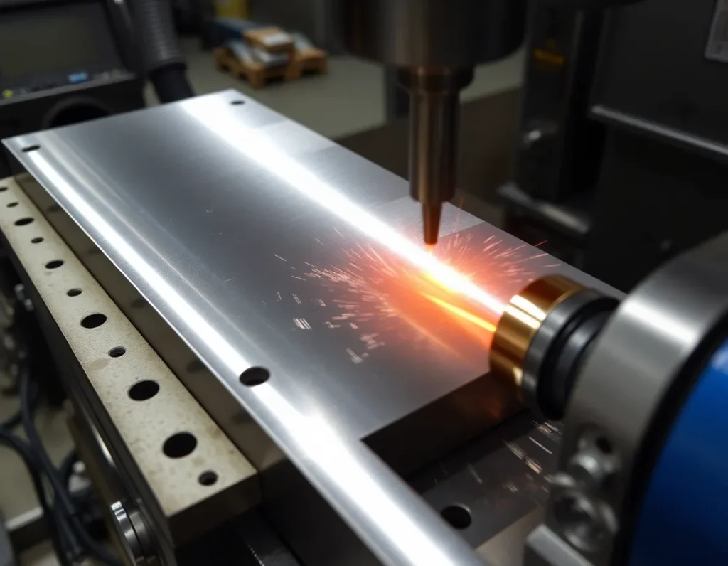
The Machining Process: From CNC Milling to 5-Axis Fabrication
The creation of a precision lidar housing follows a meticulously planned machining workflow, leveraging advanced computer numerical control (CNC) technology. The process begins with a solid billet of the chosen material, securely fixtured to a machine bed. 3-axis CNC milling is the workhorse, using rotating cutting tools to remove material from the top and sides of the part to create the basic envelope, internal cavities, and most mounting features. For more complex geometries involving undercuts or compound curves, 5-axis CNC machining becomes essential. A 5-axis machine can dynamically orient the cutting tool or the part itself along five different axes simultaneously. This allows for the creation of intricate, monolithic structures in a single setup—such as a housing with integrated cooling channels and complex optical mounts—dramatically reducing errors that can accumulate from re-fixturing the part across multiple machines.
High-speed machining (HSM) techniques are often employed, using smaller cutting tools at very high spindle speeds to achieve superior surface finishes and tighter tolerances while minimizing residual stress in the material. For the smallest, most delicate features, like tiny threaded holes for optic screws or fine vent patterns, precision drilling and tapping operations are performed with micro-tools. Throughout the process, strategic sequences of roughing, semi-finishing, and finishing passes are used to efficiently remove material while progressively achieving the final, critical dimensions and surface quality specified in the design. This orchestrated approach ensures the structural integrity and geometric perfection of the final housing.
Surface Finishing and Coatings: Ensuring Durability and Signal Clarity
Once machining is complete, the raw metal part undergoes surface finishing and coating processes that are vital for both durability and optical performance. These treatments address the microscopic imperfections left by cutting tools and prepare the housing for long-term service in challenging environments.
For aluminum housings, anodizing is the most common surface treatment. This electrochemical process thickens the natural oxide layer on the aluminum, creating a hard, wear-resistant, and corrosion-resistant surface. Anodizing also provides electrical insulation and can be dyed in various colors (most commonly black) to aid in light absorption and reduce internal reflections or “stray light” that could interfere with the lidar’s receiver. For applications requiring maximum corrosion resistance, such as marine lidar, a chromate conversion coating (Alodine) may be applied before painting or powder coating.
Powder coating provides a thick, durable, and aesthetically pleasing polymer layer that offers excellent protection against chemicals, UV radiation, and abrasion. The interior of the housing is often finished with a matte black texture specifically engineered to be optically absorptive, acting as a light trap to eliminate any stray reflections within the chamber. For the critical aperture window, anti-reflective (AR) coatings are applied to the optical-grade glass or polymer. These multi-layer thin-film coatings are designed to minimize reflection losses at the specific wavelengths of the lidar laser, ensuring maximum signal strength is transmitted out to the target and back to the receiver. Together, these finishing steps seal the precision-machined part, safeguarding it against the elements and optimizing the optical pathway for clear, reliable data acquisition.
Quality Control and Metrology: Verifying Precision for Reliable Lidar Data
The integrity of a lidar system is only as good as the verification of its housing. Following the meticulous machining and finishing processes, a rigorous regime of quality control and metrology ensures that every dimensional specification and performance requirement is met. This phase transforms a precision-machined part into a certified component ready for integration into a mission-critical sensor. The process begins with First Article Inspection (FAI), a comprehensive validation of the initial parts from a production run against all design drawings and specifications. This establishes a baseline for the manufacturing process.
Advanced coordinate measuring machines (CMMs) are the workhorses of this verification. These systems use touch probes or, increasingly, non-contact laser scanners to capture millions of data points from the housing’s surface. The point cloud is then compared to the original CAD model, generating a color-coded deviation map that visually highlights any areas outside the specified tolerances. For critical features like the optical window seat, mounting interfaces, and sealing surfaces, CMM analysis confirms flatness, perpendicularity, and true position within microns. Optical comparators and vision measurement systems are also employed for rapid 2D dimensional checks of holes, slots, and profiles.
Beyond geometry, functional testing is paramount. Hermeticity testing, often using helium leak detectors or pressure decay methods, verifies the integrity of seals and the housing’s ability to meet its IP (Ingress Protection) or NEMA rating. This is non-negotiable for housings destined for automotive or outdoor environments. Thermal cycle testing subjects the housing to extreme temperature fluctuations, checking for any deformation, seal failure, or degradation of coatings that could occur in real-world use from desert heat to arctic cold. Finally, the effectiveness of the interior anti-reflective coating and the exterior optical coatings is verified using spectrophotometers to measure reflectivity at the lidar’s specific laser wavelengths. This end-to-end validation chain closes the loop on lidar housing machining, guaranteeing that the physical enclosure supports, rather than compromises, the generation of reliable, high-fidelity point cloud data.
Applications Across Industries: Automotive, Robotics, Surveying, and More
The demand for precision-machined lidar housings is driven by its explosive adoption across diverse sectors, each with unique environmental and performance demands. The housing is the common denominator, adapting to protect the core technology whether it’s on a highway, a factory floor, or an airborne drone.
Automotive and Autonomous Vehicles
This is the most demanding and high-volume application. Automotive lidar housings must withstand brutal conditions: constant vibration, thermal shock from -40°C to 85°C, exposure to road chemicals, salt spray, and high-pressure car washes. They are typically compact, aerodynamically integrated units machined from die-cast or forged aluminum for strength-to-weight ratio. The machining tolerances for the window interface are exceptionally tight to prevent beam distortion, and the coatings must maintain clarity over the vehicle’s entire lifespan. Reliability here is not just about data quality but functional safety.
Robotics and Industrial Automation
From warehouse logistics robots to robotic arms performing complex tasks, lidar provides essential spatial awareness. Housings in this sector prioritize durability against incidental impacts, dust in industrial settings, and electromagnetic interference (EMI) shielding to coexist with heavy machinery. They are often designed for modularity, allowing easy integration into different robot chassis. Machining focuses on robust mounting points and precise alignment features to ensure the lidar’s field of view is perfectly calibrated to the robot’s navigation software.
Topographic Surveying and Mapping
Airborne (mounted on aircraft or drones) and terrestrial (tripod-mounted) surveying lidar systems capture vast landscapes for cartography, forestry, and civil engineering. Their housings are lightweight yet rigid, often utilizing advanced alloys or composites to minimize weight on aircraft. They feature large, high-quality optical windows and are engineered for thermal stability to prevent distortion during long survey flights. Environmental sealing is critical to protect against condensation during rapid altitude changes.
Other Key Applications
- Smart Infrastructure: Lidar units for traffic monitoring and smart city applications require housings with built-in thermal management for continuous operation and vandal resistance.
- Defense and Security: Housings for these applications emphasize extreme ruggedization, stealth characteristics (reduced radar signature), and operation in broad temperature extremes.
- Archaeology and Cultural Heritage: Portable, high-resolution scanners need compact, lightweight housings that protect delicate optics during transport and use in remote locations.
In each case, the machining process is tailored not just to the material, but to the end-use environment, ensuring the lidar sensor within performs flawlessly wherever it is deployed.
Future Trends and Innovations in Lidar Housing Design and Manufacturing
The evolution of lidar technology is inextricably linked to advancements in how its housing is designed and built. The future points toward greater integration, smarter materials, and more sustainable, efficient production.
A dominant trend is the move toward multi-sensor fusion housings. Instead of separate enclosures for lidar, cameras, and radar, next-generation designs incorporate precisely machined bays and alignment fiducials for all sensors into a single, unified housing. This “sensor suite” approach ensures fixed relative positions (calibration) between sensors, simplifies vehicle integration, and improves aesthetics. Machining such complex, multi-functional parts will increasingly rely on 5-axis and even 7-axis CNC systems to create internal geometries and compound angles in a single setup.
Material science is driving another major shift. While aluminum remains a staple, the use of advanced composites like carbon fiber reinforced polymers (CFRP) is growing. These materials offer exceptional stiffness and low thermal expansion, crucial for maintaining alignment, at a fraction of the weight of metal. Machining composites requires specialized tooling and processes to prevent delamination, creating a new niche in manufacturing expertise. Furthermore, the integration of additive manufacturing (3D printing) for production parts, particularly using metals like aluminum or titanium alloys, allows for previously impossible organic shapes that optimize airflow, heat dissipation, and weight distribution in one consolidated part, reducing assembly steps.
Finally, the manufacturing process itself is becoming more intelligent. The integration of in-process metrology directly on CNC machine tools allows for real-time measurement and compensation during machining, virtually eliminating post-process rework. Digital thread and IoT connectivity will ensure every housing has a complete digital twin, tracing its material history, machining parameters, and quality data throughout its life cycle. As lidar scales to consumer-level applications, these innovations in housing design and lidar housing machining will be pivotal in achieving the required combination of high performance, durability, and cost-effectiveness.
Summary of Key Points
Lidar housing machining is a critical, precision-driven discipline that bridges advanced design and real-world functionality. The housing is far more than a simple box; it is an opto-mechanical system integral to the sensor’s performance. Key takeaways include:
- Precision is Non-Negotiable: Machining tolerances directly impact beam alignment, thermal management, and sealing, which in turn affect the accuracy, range, and reliability of the lidar data.
- Material Selection is Strategic: The choice between aluminum alloys, advanced composites, or specialized polymers is driven by application-specific needs for weight, strength, thermal conductivity, and EMI shielding.
- Process Capability is Essential: Modern manufacturing relies on multi-axis CNC machining, high-speed milling, and sophisticated fixturing to achieve the complex geometries and ultra-tight tolerances required.
- Finishing is Functional: Anodizing, powder coating, and specialized optical coatings are applied not for aesthetics alone but to ensure long-term environmental protection, thermal dissipation, and optimal light transmission with minimal internal reflection.
- Verification Validates Performance: Comprehensive quality control using CMMs, leak testers, and optical metrology certifies that every housing meets its design intent before it leaves the factory.
- Application Drives Design: From vibration-resistant automotive units to lightweight aerial survey pods, the housing’s design and machining process are meticulously tailored to its operational environment.
- Innovation is Continuous: The field is rapidly evolving toward multi-sensor fusion designs, advanced lightweight materials, additive manufacturing, and smarter, connected production processes.
Ultimately, excellence in lidar housing machining is a foundational element that allows lidar technology to deliver on its promise across automotive, robotics, mapping, and beyond, ensuring these sophisticated sensors can see the world clearly and reliably for years to come.
Frequently Asked Questions (FAQ)
What are the most critical tolerances in lidar housing machining?
The most critical tolerances typically involve the features that directly interface with the optics and the mounting to the vehicle or platform. This includes the flatness and perpendicularity of the optical window seat (often within ±0.025mm or less), the true position of mounting holes and datums, and the dimensions of sealing grooves for O-rings or gaskets. Any deviation in these areas can misalign the laser beam, compromise waterproofing, or induce mechanical stress.
Why is aluminum so commonly used for lidar housings?
Aluminum, particularly alloys like 6061-T6 and 7075-T6, offers an exceptional balance of properties: it’s lightweight, has good strength, is highly machinable, and possesses excellent thermal conductivity to help dissipate heat from internal electronics. It also accepts a variety of durable surface finishes like anodizing. This combination makes it a cost-effective and performance-optimized choice for a wide range of applications.
Can plastic be used for high-performance lidar housings?
Yes, but with careful selection. Engineering thermoplastics like PEEK (Polyether Ether Ketone) or advanced composites are used in specific scenarios, especially where weight reduction, corrosion resistance, or complex, consolidated geometries are paramount. However, they generally have higher thermal expansion coefficients and lower thermal conductivity than metals, which must be accounted for in the design. For most automotive and ruggedized applications, metal remains the standard.
How does the housing affect the lidar’s field of view (FOV)?
The housing’s aperture window and the internal clearance around the rotating or solid-state scanning mechanism define the physical limits of the FOV. The window must be large enough and positioned precisely to allow the laser beams to exit and return across their entire designed angular range without vignetting (blocking). The interior surfaces are also shaped and coated to prevent reflections from the edges of the housing from interfering with the receiver.
What is the biggest manufacturing challenge in producing these housings?
Achieving and maintaining “stack-up” tolerances across multiple, interdependent features is a significant challenge. A housing may have perfect window flatness, but if its mounting surface isn’t parallel, the entire unit will be misaligned when installed. Managing internal stresses in the material during machining to prevent subsequent warping, and ensuring consistent quality in high-volume production, are also major focuses for manufacturers.
Are there industry standards for lidar housing testing?
While there is no single universal standard, manufacturers adhere to a host of relevant standards depending on the industry. Automotive lidar housings are tested to rigorous standards like ISO 16750 (road vehicles) for vibration, shock, temperature, and humidity. Ingress protection is rated per IEC 60529 (IP Code). Specific customer requirements often define additional functional and durability tests tailored to the expected operating lifetime and environment.