
Introduction: The Critical Role of Precision in Actuator Housing Machining
In the world of motion control, the actuator is the muscle. But every muscle needs a skeleton—a robust, precisely engineered structure to contain its force, guide its movement, and protect its delicate internal components. This is the actuator housing. The machining of this critical component is not merely a manufacturing step; it is the foundational process that determines the performance, longevity, and reliability of the entire actuation system. A fraction of a millimeter of deviation, a surface finish that is too rough, or a geometric imperfection can lead to premature wear, fluid leaks, misalignment, and catastrophic system failure. In high-stakes industries like aerospace, automotive, and robotics, such failures are not an option. Therefore, actuator housing machining demands an uncompromising commitment to precision, where advanced techniques, meticulous material science, and rigorous quality control converge to create the perfect protective shell for the heart of motion.
What is an Actuator Housing? Function, Design, and Material Fundamentals
An actuator housing is the structural enclosure that contains and supports the core components of an actuator. Think of it as the engine block for a motion system. Its primary function is multifaceted: it must provide a rigid and stable frame to withstand operational forces and torques, offer precise mounting points for the actuator itself and its external connections, and often contain internal pathways for fluids (in hydraulic or pneumatic actuators) or provide shielding for electrical components. The design is inherently complex, integrating features like bore cavities for pistons or gears, threaded ports for fluid lines or sensors, mounting flanges with intricate bolt patterns, and sealing surfaces that must be flawlessly flat or cylindrically true.
Design considerations are driven by the actuator type—linear, rotary, hydraulic, pneumatic, or electric. A hydraulic cylinder housing, for example, is dominated by a high-precision internal bore that must maintain a perfect seal with a piston. An electric motor actuator housing, conversely, focuses on features for bearing seats, stator mounting, and heat dissipation. Regardless of type, the housing’s design is a direct blueprint for its machining challenges, dictating the need for deep-hole drilling, fine threading, complex contouring, and exceptional surface integrity. The choice of material is the first critical decision in this chain, setting the stage for the machining process and the component’s final properties.
The Actuator Housing Machining Process: A Step-by-Step Technical Breakdown
The journey from a raw material blank to a finished actuator housing is a symphony of coordinated machining operations. It begins with comprehensive planning and CNC programming, where the 3D CAD model is translated into machine tool paths, factoring in tool selection, cutting speeds, and fixturing strategies.
1. Material Preparation and Rough Machining
The process starts with a stock piece—a forging, casting, or billet of the selected metal. This blank is first machined to create a uniform starting geometry, often on a lathe or mill, to establish primary datums (reference surfaces). Rough machining then follows, where the bulk of the material is removed rapidly using aggressive cuts. The goal here is not precision but efficiency, getting the part close to its final shape while leaving a small, consistent amount of material—known as stock allowance—for subsequent finishing operations.
2. Primary Feature Creation
With the rough shape established, machining of the housing’s key functional features begins. This stage typically involves operations like:
- Boring: For hydraulic or pneumatic cylinders, single-point boring tools are used to create the main internal diameter with extreme straightness and roundness.
- Milling of Flanges and Mounts: CNC milling machines carve out the mounting faces, bolt hole circles, and external contours.
- Drilling and Tapping: Holes for ports, sensors, vents, and mounting bolts are drilled and then threaded with precision taps.
3. Semi-Finishing and Stress Relief
After the primary metal removal, the part may undergo a stress-relief heat treatment. The aggressive cutting of rough machining can induce internal stresses in the material, which could cause distortion later. Baking the part at a controlled temperature relieves these stresses. Semi-finishing operations then remove the minimal stock left after roughing, bringing the part even closer to its final dimensions and preparing it for the high-precision finish passes.
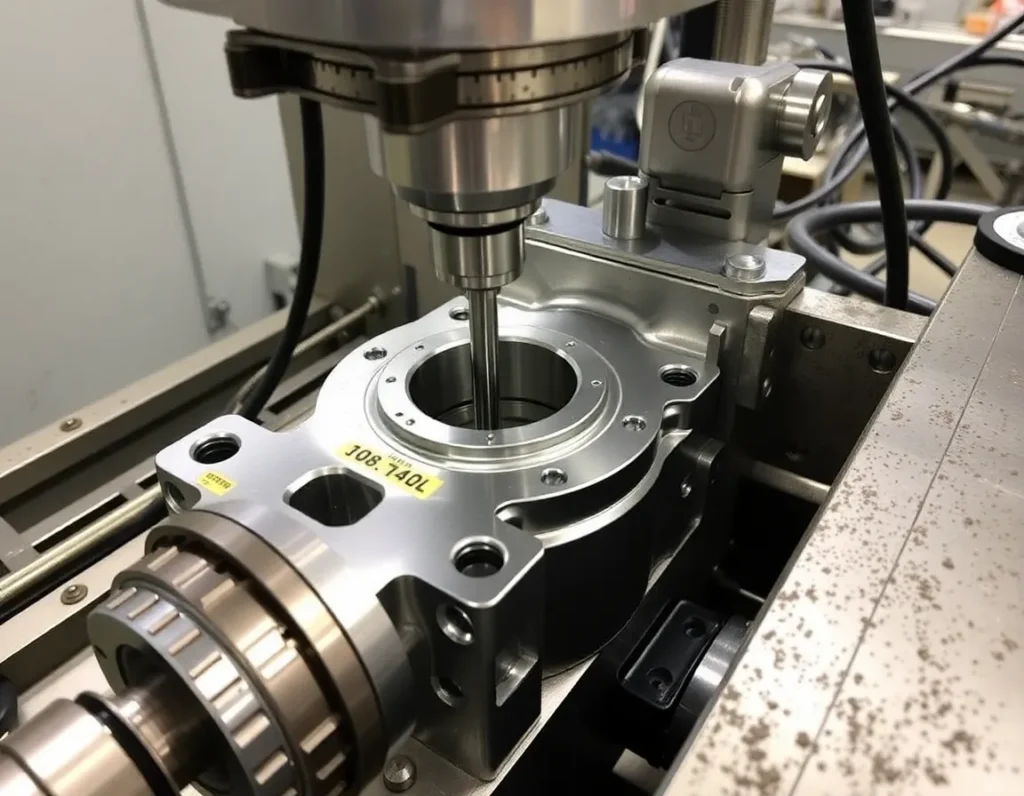
4. Finishing and High-Precision Machining
This is the most critical phase. Using sharp tools, light cuts, and optimized parameters, machinists achieve the final tolerances and surface finishes. Operations here include fine boring, honing (for exceptional surface finish on bores), precision turning of diameters, and finish milling of sealing surfaces. This stage directly impacts the housing’s sealing capability, friction characteristics, and fatigue life.
5. Secondary Operations and Inspection
Once machining is complete, secondary operations may be performed. These include deburring (removing sharp edges), washing, applying non-destructive testing (like dye penetrant inspection for cracks), and potentially surface treatments like anodizing (for aluminum) or plating. Crucially, the part is then subjected to a full inspection using coordinate measuring machines (CMM), optical comparators, and surface profilometers to verify every dimension and tolerance against the engineering drawing.
Key Machining Techniques: CNC Milling, Turning, and Multi-Axis Operations
Modern actuator housing machining is dominated by computer numerical control (CNC) technology, which provides the repeatability, complexity, and speed required for these components.
CNC Milling
CNC milling is the workhorse for creating complex geometries, flat surfaces, pockets, and contours. A rotating cutting tool moves along multiple linear axes (X, Y, Z) to remove material. For housings, 3-axis milling is used for simpler features, but the complexity often demands more. 3+2 axis milling, where the cutting tool can be oriented at a fixed angle, allows for machining multiple sides of a part in a single setup, improving accuracy and reducing handling time.
CNC Turning
Performed on lathes, turning is essential for machining rotational symmetries. The workpiece spins while a stationary cutting tool shapes it. This is the primary technique for creating the external diameters, faces, and internal bores of cylindrical housing components. Live tooling on modern CNC lathes—where rotating milling tools are integrated—allows for drilling and milling operations to be completed in the same setup, a process known as turn-mill machining. This is incredibly efficient for parts that combine cylindrical and prismatic features.
Multi-Axis Machining (5-Axis)
For the most complex actuator housings with compound angles, deep cavities, or contoured surfaces, 5-axis CNC machining is indispensable. The cutting tool can move linearly along three axes while simultaneously rotating on two additional axes. This allows the tool to approach the workpiece from virtually any direction in a single, continuous motion. The benefits are profound: the ability to machine intricate geometries otherwise impossible, drastically reduced setups, improved tool life due to optimal cutting angles, and superior surface finish. For a housing with angled ports, sculpted cooling fins, or non-orthogonal mounting features, 5-axis machining is often the only viable production method.
Material Selection for Actuator Housings: Aluminum, Steel, Stainless Steel, and Composites
The performance envelope of an actuator housing is defined by its material. The selection is a careful balance of strength, weight, corrosion resistance, machinability, and cost.
Aluminum Alloys (e.g., 6061-T6, 7075-T6)
Aluminum is the go-to choice for applications where weight savings are critical, such as in aerospace and robotics. Alloys like 6061-T6 offer an excellent strength-to-weight ratio, good corrosion resistance, and outstanding machinability, allowing for high-speed cutting and complex geometries. 7075-T6 is even stronger, approaching the strength of some steels, but can be slightly more challenging to machine. Aluminum is often anodized for enhanced surface hardness and corrosion protection.
Steel Alloys (e.g., 4140, 4340)
For high-strength, high-load applications in industrial automation and heavy-duty automotive systems, alloy steels are preferred. Grades like 4140 pre-hardened steel provide excellent toughness and fatigue strength, capable of withstanding significant shock and dynamic loads. While heavier than aluminum, steel offers superior durability in harsh environments. Machining steel requires more power and slower speeds than aluminum, and parts are often heat-treated (quenched and tempered) after machining to achieve their final mechanical properties.
Stainless Steel (e.g., 304, 316, 17-4 PH)
When corrosion resistance is paramount—in marine environments, chemical processing, or food and beverage automation—stainless steel is selected. Austenitic grades like 304 and 316 offer excellent corrosion resistance but are relatively soft and can be gummy during machining, requiring specialized tools and techniques. Precipitation-hardening grades like 17-4 PH offer a unique combination: they can be machined in a softer state and then heat-treated to achieve high strength while retaining good corrosion resistance, making them ideal for critical aerospace and defense housings.
Composites and Advanced Materials
In cutting-edge applications, particularly where extreme weight reduction or specific thermal/electrical properties are needed, composites like carbon fiber reinforced polymers (CFRP) are emerging. While not typically “machined” in the traditional metal-cutting sense, they are precision-milled and drilled using diamond-coated tools. Their use in actuator housings is currently specialized but growing, especially in high-performance sectors where every gram counts. The choice of material ultimately dictates the entire actuator housing machining strategy, from tooling and coolant to speeds, feeds, and post-processing requirements.
Tolerances, Surface Finishes, and Geometric Dimensioning (GD&T) for Optimal Performance
The precision of actuator housing machining is quantified and controlled through a strict regime of dimensional tolerances, surface finish specifications, and geometric dimensioning and tolerancing (GD&T). These are not mere numbers on a drawing; they are the engineering language that guarantees the housing will perform its sealing, alignment, and load-bearing functions under real-world conditions.
Tolerances define the permissible limit of variation in a physical dimension. For a bore that must accept a bearing, a tolerance might be specified as ±0.01mm or even tighter. Loose tolerances can lead to play, vibration, and premature wear, while excessively tight tolerances can make manufacturing prohibitively expensive and slow. The key is specifying tolerances that are “fit for function.” Critical sealing surfaces, bearing seats, and mounting interfaces demand the tightest tolerances, often in the range of a few microns, while non-critical external features may have more relaxed specifications to control cost.
Surface finish, measured in microns (µm) or microinches (µ-in), is equally critical. A rough surface on a sealing face will leak; a rough bore will abrade a moving piston rod. Finishes like 0.8 µm Ra (32 µ-in) are common for dynamic seals. Achieving these finishes often requires a multi-stage process: initial machining leaves a rougher surface, which is then refined through precision boring, grinding, or honing. The chosen finish directly impacts friction, corrosion resistance, and fatigue life.
Geometric Dimensioning and Tolerancing (GD&T) is the sophisticated system that moves beyond simple +/- tolerances on dimensions. It controls the form, orientation, location, and runout of features. For an actuator housing, GD&T is indispensable. Flatness tolerances ensure a mounting face sits flush without distortion. Perpendicularity controls ensure ports are square to the sealing surface. True position tolerances define a virtual zone within which the axis of a bore must lie, ensuring perfect alignment of internal components. Concentricity and runout tolerances guarantee that rotating or reciprocating parts move smoothly without binding. By using GD&T, engineers communicate the design intent clearly, ensuring the manufactured housing has the correct geometry, not just the correct dimensions, for flawless assembly and operation.
Quality Control and Inspection: Ensuring Precision and Reliability in Every Housing
Adherence to the stringent specifications outlined in the design phase is verified through a rigorous quality control and inspection protocol. This process transforms a machined block of metal into a certified, reliable actuator housing ready for duty.
Inspection begins at the receiving stage with material certification review. First Article Inspection (FAI) is a critical milestone, where a fully documented inspection of the first part off the production line is conducted against all drawing requirements. This validates that the machining process, tooling, and programming are capable of producing a conforming part. Once production is approved, in-process inspections are conducted at key stages. Operators use calibrated hand tools like micrometers, calipers, and dial indicators to check critical dimensions and features during machining, allowing for immediate corrections and preventing the production of non-conforming parts.
For the most critical features and to verify GD&T, advanced metrology equipment is employed. Coordinate Measuring Machines (CMM) use a tactile probe or laser to collect precise point data from the housing’s surface. This data is compared to the CAD model, generating a detailed report on dimensional accuracy, geometric tolerances, and form. Optical comparators and vision measuring systems provide fast, accurate 2D measurements of profiles and hole patterns. Surface roughness testers, using a diamond-tipped stylus, quantitatively measure the Ra (average roughness) and other finish parameters to ensure sealing surfaces meet spec.
Beyond dimensional checks, non-destructive testing (NDT) methods are often required, especially for high-integrity applications. Dye penetrant inspection can reveal surface-breaking cracks or porosity. For critical aerospace or defense housings, more advanced techniques like X-ray or CT scanning might be used to detect internal flaws invisible to the eye. The final step is often a functional test, such as a pressure or leak test, where the housing is assembled with plugs and subjected to air or fluid pressure to verify its integrity as a sealed vessel. This multi-layered inspection approach, from raw material to finished part, creates a verifiable chain of quality that ensures every actuator housing meets its performance mandate.
Applications Across Industries: Aerospace, Automotive, Robotics, and Industrial Automation
The demand for precision-machined actuator housings spans virtually every sector of modern engineering, each with its unique set of challenges and performance requirements.
Aerospace and Defense
This sector represents the pinnacle of performance and reliability demands. Actuator housings here control flight surfaces (ailerons, rudders), landing gear, thrust vectoring, and weapon systems. Materials are high-strength, often titanium or precipitation-hardening stainless steel. Tolerances are extremely tight, and every part undergoes exhaustive inspection and traceability protocols. Weight is a primary driver, leading to complex, thin-walled designs that push multi-axis machining to its limits. Failure is not an option, making the precision and quality of the housing machining process absolutely critical.
Automotive
In the automotive industry, actuator housings are found in turbocharger wastegates, electronic throttle bodies, advanced braking systems (ESP/ABS), and increasingly in electric vehicle battery cooling and powertrain management. The focus is on high-volume production, cost-effectiveness, and robust performance under harsh environmental conditions (heat, vibration, contaminants). Aluminum alloys are prevalent for weight savings. Processes are highly automated, with a strong emphasis on statistical process control (SPC) to maintain consistency across hundreds of thousands of parts.
Robotics and Collaborative Robots (Cobots)
Robotics demands actuators that are powerful, compact, and incredibly precise. The housings for robotic joint actuators or grippers must be lightweight to improve payload and efficiency, yet stiff enough to maintain accuracy under load. Designs are often highly integrated, with the housing also serving as a structural frame component. Surface finishes for sealing are critical to keep out dust and debris. The trend towards collaborative robots places additional emphasis on sleek, safe designs with no sharp edges, influencing the final machining and finishing steps.
Industrial Automation and Machinery
This is the broadest category, encompassing housings for pneumatic and hydraulic cylinders, valve actuators, linear guides, and motor drives in factory equipment, packaging machines, and process control systems. Durability and longevity are key. Housings are often made from robust materials like carbon steel or cast iron for larger equipment. The machining must ensure perfect alignment for piston rods and shafts to prevent side-loading and seal wear. Port threads must be clean and precise to prevent leaks in hydraulic systems that operate at thousands of psi.
Summary of Key Points
Precision actuator housing machining is a foundational manufacturing discipline that enables motion control across the technological landscape. The process begins with a deep understanding of the housing’s function: to protect, align, and facilitate the operation of internal mechanisms under load. Material selection—from lightweight aluminum and strong steels to corrosion-resistant stainless grades—directly dictates the machining approach and the component’s final properties.
The machining process itself is a symphony of advanced techniques, primarily using CNC milling, turning, and multi-axis machining centers to sculpt complex geometries from solid stock. Achieving the required performance hinges on specifying and holding tight dimensional tolerances, exacting surface finishes for sealing and wear, and comprehensive geometric controls through GD&T. This precision is not assumed; it is guaranteed through a multi-stage quality control regime employing tools from hand gauges to CMMs and NDT methods.
Ultimately, the value of this precise manufacturing is realized in its applications. From the extreme environments of aerospace to the high-volume demands of automotive, the dynamic world of robotics, and the rugged realm of industrial automation, a well-machined actuator housing is a silent enabler of reliability, efficiency, and innovation. It is a component where engineering design and manufacturing excellence converge to create motion.
Frequently Asked Questions (FAQ)
What are the most common mistakes in actuator housing machining?
Common pitfalls include inadequate workholding, leading to vibration and poor surface finish; incorrect tool selection or worn tools causing dimensional inaccuracy; improper sequencing of operations that compromises stability; and neglecting thermal management, where heat from machining can warp the part, especially in thin-walled designs. A lack of in-process inspection can allow a batch of parts to be machined out of tolerance before the error is caught.
How does multi-axis machining benefit actuator housing production?
Multi-axis (5-axis) machining allows complex geometries to be produced in a single setup. This is crucial for housings with ports, bosses, or mounting features on multiple planes. It eliminates the errors that accumulate from repositioning the part between setups, improves accuracy on compound angles, and enables the machining of deeper, more intricate internal features with shorter, more rigid tools, resulting in better surface finishes and tighter tolerances.
Can you machine an actuator housing from a casting or forging?
Yes, and this is common for high-volume or very large housings. A near-net-shape casting or forging provides the basic form, which is then precision machined only on the critical sealing, bearing, and mounting surfaces. This approach significantly reduces raw material waste and machining time compared to starting from a solid block. The machining process must account for potential variation in the casting’s skin and internal structure.
What is the role of post-machining treatments?
Post-machining treatments are essential for enhancing performance. They include heat treatment (to increase strength or relieve stresses), anodizing or plating (for corrosion resistance and wear resistance), and painting or powder coating (for environmental protection and aesthetics). For sealing surfaces, specific finishes like grinding or honing are post-machining operations that achieve the required smoothness. These steps are integral to the final part specification.
How do I choose between aluminum and steel for my housing?
The choice boils down to a trade-off between strength, weight, corrosion resistance, and cost. Aluminum (e.g., 6061-T6) is the go-to for excellent strength-to-weight ratio, good machinability, and natural corrosion resistance—ideal for aerospace, robotics, and applications where weight matters. Steel (e.g., 4140) is chosen for higher strength, stiffness, and durability under extreme loads or wear, common in heavy industrial and hydraulic applications. Stainless steel (e.g., 316) is specified when corrosion resistance is the paramount concern.