The Heart of Forced Induction: Why Wheel Precision Matters
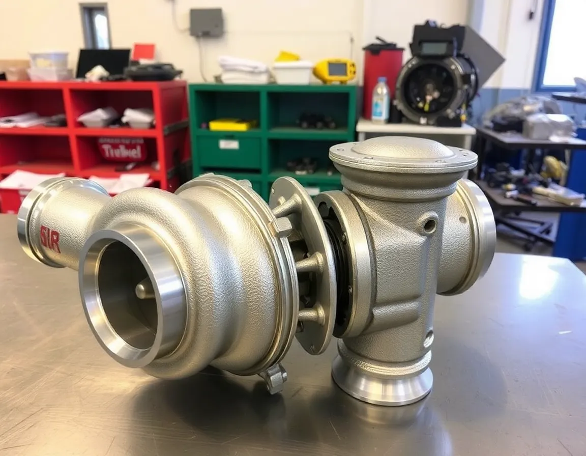
In the high-stakes world of internal combustion, the turbocharger stands as a pinnacle of energy recovery and power density. At its core, this device is deceptively simple: an exhaust-driven turbine wheel connected to a fresh-air-compressing impeller wheel. Yet, the performance, efficiency, and reliability of the entire system hinge on the microscopic perfection of these rotating components. Precision turbocharger wheel machining is not merely a manufacturing step; it is the foundational art and science that transforms raw, high-performance alloys into the beating heart of forced induction. This process dictates airflow characteristics, spool response, ultimate power potential, and operational longevity, separating a mediocre turbo from an exceptional one.
Deconstructing the Wheels: Turbine vs. Compressor
Before delving into machining, understanding the distinct roles and geometries of the two wheels is crucial. Each presents unique machining challenges.
The Turbine Wheel: Harnessing Chaotic Energy
Mounted in the hot side of the turbo, the turbine wheel is subjected to extreme temperatures (often exceeding 1050°C/1900°F) and corrosive exhaust gases. It is typically machined from nickel-based superalloys like Inconel, renowned for their heat resistance. The wheel's primary function is to efficiently convert the thermal and kinetic energy of the exhaust stream into rotational motion. Its blades are designed with a curved, often highly backswept profile to manage pulse energy and minimize inertia. Precision machining here ensures the wheel can survive this hellish environment while responding quickly to engine demands.
The Compressor Wheel: The Art of Air Sculpting
On the cold side, the compressor wheel's job is to draw in, accelerate, and pressurize intake air. Made from high-strength aluminum alloys (like 4032 or 2618) or titanium for extreme applications, it operates at high rotational speeds but lower temperatures. Its geometry is far more complex, featuring highly contoured, swept-back blades with inducer and exducer sections. The leading edges must be razor-sharp for clean airflow entry, while the exducer profile and the critical "blade tip to housing" clearance determine efficiency and surge limits. Any imperfection in this aerodynamic sculpture directly translates to lost power and heat.
The Precision Machining Workflow: From Billet to Balanced Rotor
Creating a turbocharger wheel is a multi-stage, meticulously controlled process. Modern CNC (Computer Numerical Control) machining is the undisputed standard, offering the repeatability and accuracy required.
1. Material Selection and Initial Preparation
The process begins with a forged or cast billet of the chosen alloy. Forging is preferred for high-performance applications as it creates a superior grain structure, enhancing strength and fatigue resistance. This billet is often pre-turned to a rough shape before the detailed machining begins.
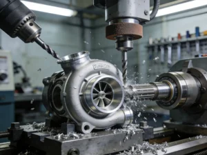
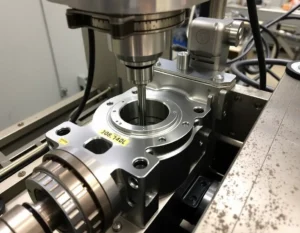
2. Multi-Axis CNC Machining: The Core of Precision
This is where the wheel takes shape. State-of-the-art 5-axis CNC milling machines are essential. They allow the cutting tool to approach the workpiece from virtually any direction, which is mandatory for the complex, undercut geometries of compressor and turbine blades.
- Roughing: Aggressive cuts remove large amounts of material to establish the basic wheel form.
- Semi-Finishing: Refines the shape closer to final dimensions, leaving a small amount of stock for the finishing pass.
- Finishing: The most critical phase. Using specialized micro-grain carbide or diamond-tipped tools, the machine traces the exact aerodynamic profiles with tolerances often held within ±0.01mm (0.0004 inches) or less. Surface finish is paramount here.
3. Critical Features and Post-Machining Processes
Once the blades and hub are machined, other vital operations follow:
- Hub Bore and Nut Thread Machining: The interface with the shaft must be perfectly concentric and sized for a friction-fit (often with a slight interference) before being friction-welded or bolted.
- Balancing Preparation: The wheel is often lightly balanced at this stage (single-plane balancing) before assembly with the shaft.
- Surface Treatments (Optional): Compressor wheels may be anodized for corrosion protection, while turbine wheels might receive specialized coatings to further enhance heat and oxidation resistance.
4. Assembly and Final Dynamic Balancing
The machined wheel is assembled with its shaft to form the CHRA (Center Housing Rotating Assembly) core. This assembly then undergoes high-speed dynamic balancing. It is spun at operational speeds (often 100,000+ RPM) in a vacuum chamber, and minute amounts of material are laser-etched or ground away from specific points to eliminate any vibrational imbalance. This step is non-negotiable for durability.
The Tangible Benefits of Micron-Level Precision
Investing in ultra-precise machining yields measurable performance and reliability gains across the board.
Performance and Efficiency Gains
A precisely machined wheel with optimal blade profiles and clearances moves air more effectively. This translates to:
- Reduced Turbo Lag: Lower rotational inertia from a perfectly shaped, lightweight wheel means faster spool-up.
- Higher Adiabatic Efficiency: More of the engine's power is used to make boost, not heat. Cooler, denser intake air supports more power and reduces engine knock risk.
- Extended Operating Range: Improved aerodynamics can widen the compressor map, delaying surge and choke limits, giving the engine a broader, more usable powerband.
Enhanced Durability and Reliability
Precision is a cornerstone of robustness:
- Minimized High-Cycle Fatigue: Perfectly smooth surfaces and radii eliminate stress concentrators where cracks can initiate.
- Optimal Clearance Control: Precise blade tips prevent contact with the housing during thermal expansion, avoiding catastrophic failure.
- Perfect Balance: A dynamically balanced rotor assembly minimizes bearing load and vibration, dramatically extending the life of the entire CHRA.
Applications and Best Practices in the Industry
Precision-machined turbo wheels are demanded across the spectrum of motorsport and high-performance engineering.
Key Applications: From Formula 1 and World Rally Championship cars, where every millisecond of response is critical, to diesel heavy-haul trucks prioritizing fuel economy and longevity. The aftermarket performance sector relies on precision-machined billet wheels for upgraded turbos, and the burgeoning field of hybridized turbochargers (e-turbos) demands exceptionally balanced, low-inertia rotors for electric motor integration.
Best Practices for Manufacturers and End-Users
- For Machinists: Invest in high-rigidity, multi-axis CNC platforms. Utilize advanced CAM software for optimal tool paths. Implement rigorous in-process measurement with CMMs (Coordinate Measuring Machines) and surface profilometers. Maintain a controlled environment to mitigate thermal expansion of workpieces and machines.
- For Engine Builders & Tuners: Always source wheels and turbos from reputable manufacturers who transparently discuss their machining and balancing standards. Never compromise on balancing quality. Ensure proper installation with clean, oil-fed lines and appropriate filtration to protect the finely machined components from abrasive damage.
Conclusion: The Invisible Edge
While the external housing of a turbocharger may look impressive, the true masterpiece lies within. Precision turbocharger wheel machining is the disciplined application of advanced manufacturing to the laws of fluid dynamics and material science. It is an endeavor where microns matter, surfaces tell a story, and balance is everything. The result is an component that delivers not just brute force, but responsive, efficient, and reliable power—transforming exhaust gas from a mere waste product into the very breath of high performance. In the relentless pursuit of power and efficiency, the precision of the cut defines the edge of possibility.