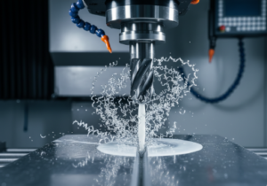
What is Peripheral Milling? The Foundation of Surface Finishing
In the world of machining, achieving a pristine, flawless surface finish is often the hallmark of quality and precision. Among the arsenal of milling techniques, peripheral milling stands out as a fundamental and exceptionally effective method for this very purpose. Also commonly referred to as slab milling or plain milling, this process is defined by the orientation of the cutting tool relative to the workpiece. In peripheral milling, the axis of the cutter rotation is parallel to the workpiece surface being machined. The primary cutting action is performed by the teeth located on the periphery (the cylindrical surface) of the milling cutter. This geometry allows for long, sweeping engagements ideal for creating flat surfaces, slots, and profiles with exceptional accuracy and surface integrity.
Unlike face milling, where the cutting action is primarily from the bottom of the tool, peripheral milling leverages the side of the cutter. This characteristic makes it the go-to choice for machining deep slots, accurate contours, and large flat surfaces where the width of the cut is defined by the cutter's axial depth. Understanding and mastering this technique is crucial for any machinist or manufacturing engineer aiming to optimize part quality, tool life, and overall machining efficiency.
How Peripheral Milling Works: Mechanics and Methods
The mechanics of peripheral milling are elegant in their simplicity but powerful in application. A cylindrical cutter, mounted on an arbor, rotates at high speed. The workpiece is fed linearly in a direction parallel to the cutter's axis, or at a slight angle for specific operations. The individual teeth of the cutter engage the workpiece material, shearing away chips in a repetitive, interrupted cutting pattern.
Conventional (Up) Milling vs. Climb (Down) Milling
A critical decision in peripheral milling is the direction of the workpiece feed relative to the cutter rotation. This defines two primary methods, each with distinct advantages and considerations:
- Conventional Milling (Up Milling): The workpiece is fed against the direction of the cutter rotation. The chip thickness starts at zero and increases to a maximum at the end of the cut. This method is known for its reduced tendency to "grab" the workpiece, making it safer for older or less rigid machines. It is often preferred for roughing operations as it subjects the machine to less shock load initially. However, the upward cutting force can lift the workpiece, requiring secure clamping, and it can produce a slightly rougher surface finish due to the chip formation process.
- Climb Milling (Down Milling):The workpiece is fed in the same direction as the cutter rotation. The chip thickness is at its maximum at the point of entry and decreases to zero. This results in several key benefits: it pulls the workpiece into the cutter, improving stability and reducing the chance of chatter; it typically produces a superior surface finish; and it can extend tool life by reducing heat generation. The primary drawback is the need for a rigid machine, a backlash-free feed mechanism, and secure workpiece holding, as the cutting forces push the workpiece downward and in the direction of feed.
Types of Peripheral Milling Cutters
The choice of cutter is paramount. Common types include:
- Plain Milling Cutters: Straight or helical teeth on the periphery for general slab milling.
- Side and Face Cutters:Have teeth on both the periphery and the side, allowing for simultaneous machining of two surfaces.
- Slotting Cutters (Slab Saws):Thin cutters designed specifically for cutting narrow slots and parting-off operations.
- Form Relieved Cutters:Used for machining complex profiles, as their tooth form is maintained even after repeated regrinding.
The Benefits and Applications of Peripheral Milling
Peripheral milling is not just a technique; it's a strategic choice driven by a clear set of advantages that make it indispensable in various manufacturing scenarios.
Key Advantages
- Excellent Surface Finish: When performed with sharp tools, correct speeds/feeds, and especially using climb milling, it can produce remarkably smooth surfaces, often reducing or eliminating the need for secondary finishing operations.
- Efficient Material Removal:It is highly effective for removing large volumes of material over long, flat surfaces or deep slots, making it efficient for both roughing and finishing.
- Versatility in Feature Creation:Beyond flat surfaces, it is the primary method for machining slots (like T-slots and dovetails), grooves, and precise edge profiles.
- Good Tool Life Management:The cutting load is distributed across multiple teeth, and with proper chip evacuation, heat dissipation is manageable, contributing to consistent tool life.
Industrial Applications
Peripheral milling is ubiquitous across industries. You will find it in action when:
- Machining the large, flat surfaces of engine blocks, pump housings, and machine tool beds.
- Cutting deep slots for keys, splines, or seals in shafts and gears.
- Creating intricate profiles on molds and dies.
- Producing precise grooves and ledges in aerospace components and automotive parts.
- General-purpose milling in job shops for creating shoulders, steps, and square edges on blocks of metal, plastic, or composite materials.
Best Practices for Mastering Flawless Surfaces
To truly master peripheral milling and achieve those coveted flawless surfaces, attention must be paid to a combination of machine setup, tool selection, and operational parameters.
Machine Rigidity and Setup
Rigidity is non-negotiable.Any deflection in the machine, spindle, arbor, or workpiece will translate directly into poor surface finish, chatter marks, and dimensional inaccuracy. Ensure the workpiece is clamped securely and supported against cutting forces. Use the shortest possible cutter and arbor that can complete the job to maximize stiffness. For climb milling, verify that your machine's ball screws have minimal or no backlash to prevent the workpiece from being pulled into the cutter uncontrollably.
Tooling Selection and Maintenance
Select a cutter with the appropriate diameter, number of teeth, and helix angle for your material. A higher helix angle (e.g., 45°) promotes smoother shearing and is excellent for finishing. Use sharp, high-quality inserts or a freshly sharpened solid carbide/HSS cutter. For finishing, consider a wiper flat on the insert—a small flat area behind the cutting edge that burnishes the surface for an exceptional finish. Always ensure the cutter is balanced, especially at high RPMs.
Optimizing Cutting Parameters (Speeds & Feeds)
This is the heart of process optimization. Use the following guidelines:
- Spindle Speed (RPM): Calculate based on the cutter's diameter and the recommended surface speed (SFM) for your workpiece material. Too slow can cause rubbing and poor finish; too fast can overheat the tool.
- Feed Rate (IPM):This is critical for chip load. Aim for an optimal chip thickness per tooth. A feed that is too low can cause the tool to rub and work-harden the material, while a feed that is too high can cause tool breakage and a rough finish. For finishing, a consistent, light chip load is key.
- Depth of Cut:For finishing, use a light radial depth of cut (stepover)—often 5-10% of the cutter diameter—with a full axial depth. This minimizes tool pressure and deflection, allowing for a clean, accurate cut.
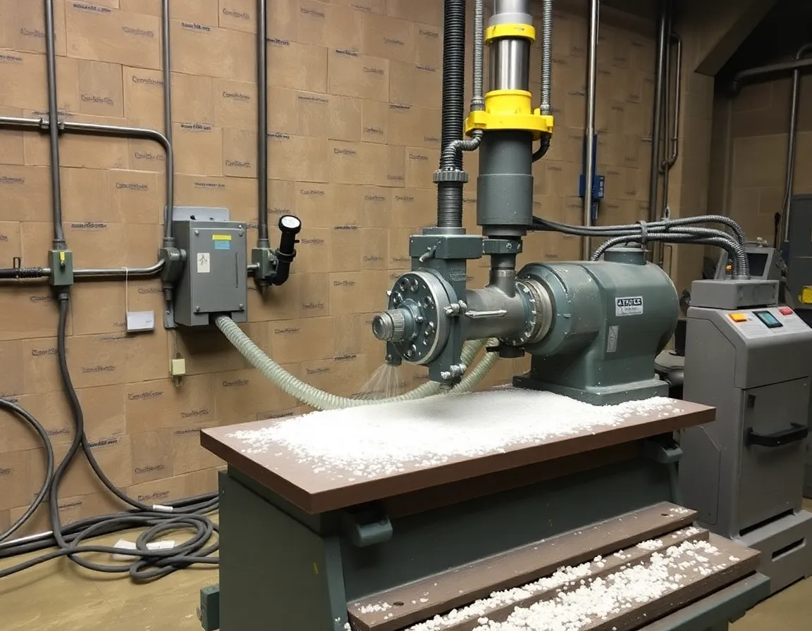
Coolant and Chip Evacuation
Effective cooling and lubrication are vital, especially in finishing passes. Coolant helps control heat at the cutting edge, prevents built-up edge, and improves surface finish. In peripheral milling, chips can get trapped in the cut. Use ample coolant pressure or air blast to evacuate chips promptly, preventing them from being re-cut, which is a primary cause of poor surface finish and tool damage.
The Finishing Pass Strategy
Always leave a small, consistent amount of stock (e.g., 0.010-0.020 inches) for a final finishing pass. This pass should be performed with a sharp tool, optimized parameters, and preferably using the climb milling direction. A single, clean finishing pass will yield a far better result than trying to achieve both size and finish in one aggressive cut.
By deeply understanding the principles of peripheral milling, respecting the importance of rigidity, and meticulously applying these best practices, you can transform this fundamental machining process into a reliable method for producing parts with exceptional dimensional accuracy and flawless, high-quality surfaces. It remains a cornerstone skill in precision manufacturing, proving that mastering the basics is often the most advanced strategy of all.