Introduction: The Quest for Thermal Management Excellence
In the relentless pursuit of smaller, faster, and more powerful electronic devices, managing waste heat has become a paramount engineering challenge. Excessive heat degrades performance, reduces reliability, and shortens the lifespan of critical components. While various cooling solutions exist, precision machined heat sinks stand out as the gold standard for high-performance, high-reliability applications. Unlike their cast or extruded counterparts, machined heat sinks are carved from a solid block of material using advanced Computer Numerical Control (CNC) equipment, offering unparalleled design freedom and thermal performance. This guide delves into the world of precision machined heat sinks, exploring their mechanics, advantages, applications, and best practices for implementation.
What Are Precision Machined Heat Sinks?
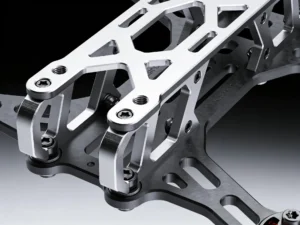
A precision machined heat sink is a thermal management device manufactured by subtractive processes—primarily milling, turning, and drilling—starting from a solid billet of metal. CNC machines follow digital blueprints with extreme accuracy, removing material to create intricate fin arrays, complex base geometries, and integrated features that are impossible to achieve with other mass-production methods.
Core Materials and Their Impact
The choice of material is fundamental to the heat sink's performance. Machining allows for the use of high-performance alloys that may be difficult or impossible to form by other means.
- Aluminum (6061, 6063, 7075): The most common choice due to its excellent balance of thermal conductivity, lightweight, machinability, and cost. 6061 is the industry workhorse.
- Copper (C110, C101): Offers superior thermal conductivity (nearly double that of aluminum), making it ideal for the most demanding thermal challenges. Its higher density and cost, along with greater machining difficulty, are trade-offs.
- Aluminum-Copper Alloys & Composites: Materials like aluminum with copper cores or tungsten-copper composites are used in specialized applications to tailor thermal expansion or conductivity.
The Machining Process: From Billet to Finished Product
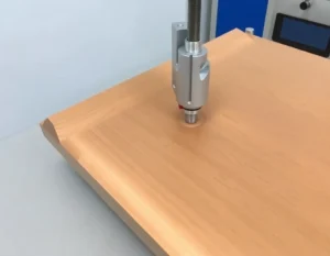
The process begins with a 3D CAD model. This digital design is translated into machine instructions (G-code). A solid billet is then fixtured into a CNC mill or lathe. Using a variety of cutting tools, the machine precisely sculpts the part, creating:
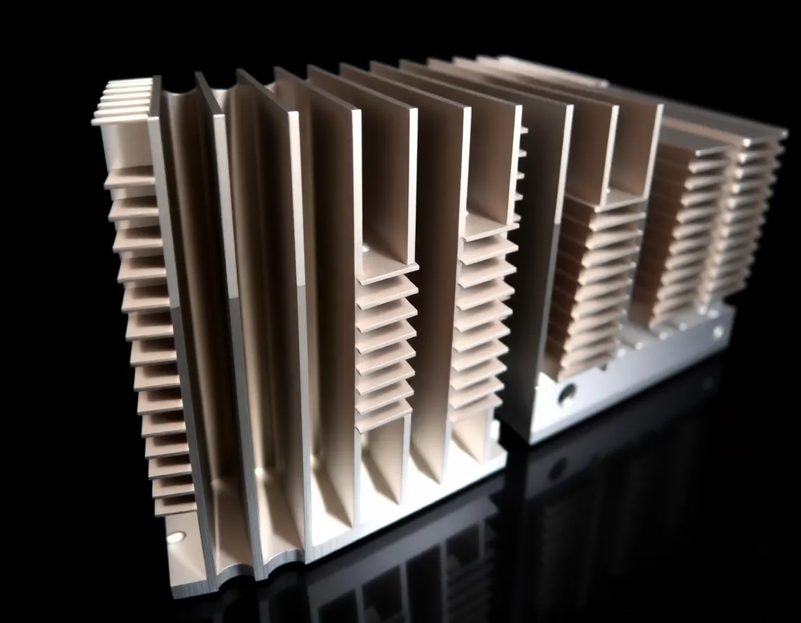
- Complex Fin Geometries: Ultra-thin, tall fins; tapered fins; or pin-fin arrays that maximize surface area.
- Asymmetric Designs: Fins and features that conform to irregular space constraints within an assembly.
- Integrated Features: Holes for mounting, steps for component clearance, grooves for thermal interface material (TIM), or channels for liquid cooling—all created in a single setup, ensuring perfect alignment.
Secondary operations like deburring, surface finishing (e.g., anodizing for aluminum, nickel plating for copper), and thermal testing complete the manufacturing cycle.
Key Benefits and Advantages of Machining
Why choose a machined heat sink over a cheaper extruded or stamped alternative? The benefits are substantial for demanding applications.
Unmatched Design Flexibility and Precision
This is the primary advantage. CNC machining can produce virtually any geometry the designer can conceive. This allows for optimized thermal performance through custom fin shapes and layouts, and perfect mechanical integration with the heat source and surrounding enclosure. Tolerances can be held to thousandths of an inch, ensuring a flawless fit.
Superior Thermal Performance
The ability to create thinner, closer-spaced, and taller fins results in a significantly larger surface area for heat dissipation within a given footprint. Furthermore, machined heat sinks are made from a single piece of metal, eliminating the thermal interface resistance found in bonded or soldered assemblies. The base can be made exceptionally flat, minimizing thermal impedance at the critical component interface.
High Structural Integrity and Reliability
Being monolithic, machined heat sinks have no weak points from joining processes. They exhibit excellent mechanical strength, vibration resistance, and durability. This makes them ideal for harsh environments like aerospace, defense, and automotive applications.
Rapid Prototyping and Low-Volume Agility
While unit cost is higher than mass-produced alternatives, machining eliminates the need for expensive tooling (like extrusion dies). This makes it exceptionally cost-effective for prototypes, pre-production runs, and low-to-medium volume production, allowing for rapid design iteration and time-to-market.
Primary Applications and Use Cases
Precision machined heat sinks are deployed wherever thermal management is critical and performance cannot be compromised.
- Aerospace & Defense: Avionics, radar systems, and satellite components where reliability, lightweight design, and performance under extreme conditions are non-negotiable.
- High-Performance Computing (HPC) & Servers: Cooling high-wattage CPUs, GPUs, and ASICs in data centers and supercomputers. Often integrated with vapor chambers or liquid cold plates.
- Power Electronics: IGBTs, MOSFETs, and power converters in electric vehicles, renewable energy systems (solar inverters, wind turbines), and industrial motor drives.
- Medical Electronics: Imaging equipment (MRI, CT scanners), surgical lasers, and diagnostic devices where silent operation (often fanless) and absolute reliability are essential.
- Telecommunications & RF: Base station power amplifiers and high-frequency RF components that generate concentrated heat in sensitive equipment.
- Test & Measurement: Equipment requiring stable thermal conditions for accurate calibration and measurement.
Best Practices for Designing and Implementing Machined Heat Sinks
To fully leverage the potential of a precision machined heat sink, careful design and application are crucial.
Design for Manufacturability (DFM) for Machining
Collaborate early with your machining partner. Consider tool access; deep, narrow pockets may require specialized tools. Balance fin aspect ratio (height to thickness) with machinability—very thin, tall fins may be fragile. Specify appropriate tolerances; tighter tolerances increase cost. Utilize radii in internal corners (end mills are round) to reduce machining time and cost.
Optimizing Thermal and Mechanical Interface
The interface between the heat-generating component and the heat sink base is a critical bottleneck.
- Surface Flatness: Specify a machined flatness suitable for the application. A mirror finish isn't always necessary, but voids or warping will cripple performance.
- Thermal Interface Material (TIM): Select the correct TIM (grease, phase-change pad, gap filler) for the interface pressure and gap. Design grooves or reservoirs to control TIM spread and minimize bond-line thickness.
- Mounting Pressure: Ensure the mounting system provides even, sufficient pressure across the entire interface area to minimize thermal resistance. Finite Element Analysis (FEA) can model stress and deflection.
Integrating with Overall System Cooling
A heat sink does not operate in isolation. Consider the system airflow (natural or forced convection). Orient fins in the direction of airflow. For forced convection, balance fin density against fan static pressure capabilities. In dense layouts, consider the thermal shadowing effect of upstream components. For extreme heat loads, explore machining channels into the base to create a liquid-cooled cold plate—a highly effective hybrid solution.
The Value of Thermal Analysis and Prototyping
Never guess. Use Computational Fluid Dynamics (CFD) software to simulate thermal performance early in the design phase. This allows for virtual optimization of fin geometry, material choice, and airflow before a single part is cut. Always follow simulation with real-world testing of a prototype under actual or simulated load conditions to validate the model and make final adjustments.
Conclusion: A Strategic Investment in Performance
Precision machined heat sinks represent a strategic investment in the performance, reliability, and longevity of high-value electronic systems. While their unit cost is higher, the total cost of ownership is often lower when considering the avoided risks of thermal failure, reduced warranty claims, and extended product life. Their unparalleled design freedom enables engineers to solve thermal challenges in the most constrained and demanding environments, pushing the boundaries of what is electronically possible. By understanding their advantages, applications, and following best practices in design and implementation, engineers can harness the full power of machined thermal solutions to create cooler, faster, and more reliable products for the future.