The Unsung Hero of Optical Systems: The Critical Role of Precision Adapters
In the world of high-performance optics—from cutting-edge semiconductor lithography and medical imaging to aerospace surveillance and professional cinematography—the lens is often the star of the show. However, even the most exquisitely ground lens is rendered useless if it cannot be mounted with absolute precision, stability, and repeatability. This is the domain of precision lens adapter machining, a specialized field of manufacturing where microns matter and material science meets meticulous engineering. A lens adapter is far more than a simple mechanical spacer; it is the critical interface that defines the optical axis, maintains focal distances, and ensures the entire system performs to its theoretical limit. This deep dive explores the art, science, and technology behind machining these vital components.
Anatomy of a Precision Lens Adapter: More Than Meets the Eye
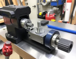
At its core, a lens adapter is a mounting interface that allows a lens cell or optical element to be securely attached to a housing, stage, or another lens. Its primary functions are mechanical registration, positional accuracy, and environmental isolation. To achieve this, its design incorporates several non-negotiable features, each demanding specific machining approaches.
Key Features and Their Machining Implications
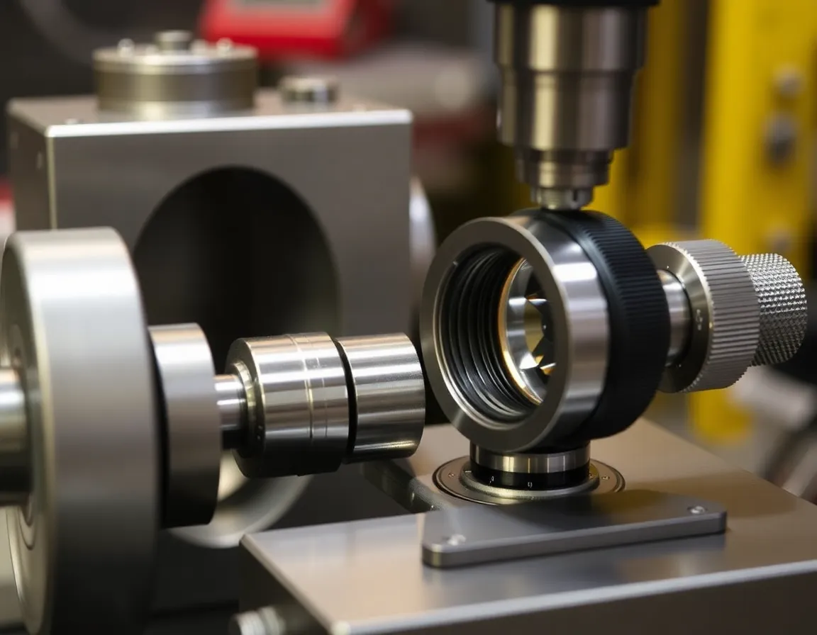
Precision Bore and Registration Surfaces: The inner diameter (bore) that contacts the lens barrel or outer diameter (OD) that fits into a housing must be machined to extremely tight tolerances, often within ±0.005mm or less. This ensures the optical axis is perfectly centered and perpendicular to the image plane. Achieving this requires high-precision CNC lathes or grinding machines with exceptional spindle truth and thermal stability.
Threading (e.g., C-Mount, T-Thread, Custom): Standardized threads like the 1"-32 UN (C-mount) or M42x1mm are common. These threads must be cut with precision to avoid "wobble" or tilt, which induces optical misalignment. Single-point threading on a CNC lathe is the gold standard, allowing for perfect thread form, pitch, and concentricity with the adapter's other features.
Flange Focal Distance (FFD) Land: This is the critical reference surface that defines the exact distance from the lens mounting plane to the sensor or image plane. The FFD must be machined with sub-micron surface finish and absolute perpendicularity to the bore. This often involves a final grinding or lapping operation after primary machining to eliminate any bow or irregularity.
Light Baffles and Anti-Reflective Features: To prevent stray light (flare) from degrading image contrast, adapters often include internal baffles, blackened grooves, or knife-edges. Machining these features requires small, sharp tools and strategies to create deep, undercut grooves without inducing vibration or tool deflection.
The Machining Workflow: From Raw Material to Optical Interface
Creating a high-precision adapter is a multi-stage process where planning and order of operations are paramount. A typical workflow for a complex adapter might proceed as follows:
1. Material Selection and Preparation
The choice of material is foundational. Common selections include:
- Aluminum 6061-T6 / 7075-T6: Lightweight, good machinability, and stable. Often used in consumer, cine, and many industrial applications. May be hard-anodized for wear and corrosion resistance.
- Stainless Steel (304, 316, 416): Offers superior strength, thermal stability, and corrosion resistance. Essential for high-load, vacuum, or harsh environments. More challenging to machine, requiring rigid equipment and appropriate tooling.
- Invar / Super Invar: A nickel-iron alloy with an exceptionally low coefficient of thermal expansion (CTE). Used in the most thermally sensitive applications like satellite optics or metrology systems where dimensional stability across temperature swings is critical.
- Brass: Excellent machinability and natural corrosion resistance, often used for custom photographic adapters and prototypes.
The material is first cut to size, stress-relieved (if necessary), and often pre-machined to a rough shape to remove bulk.
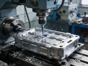
2. Primary CNC Machining Operations
This stage forms the majority of the adapter's geometry. A modern 4 or 5-axis CNC machining center allows for complete machining in one or two setups, minimizing error accumulation.
- Turning: Performed on a CNC lathe or mill-turn center to create the primary OD, bore, and front/rear faces. This ensures concentricity of these critical features.
- Milling: Used to create external flats, mounting holes, light baffles, and any non-rotationally symmetric features. 5-axis machining is invaluable for complex adapters with angled ports or integrated kinematic mounts.
- Drilling and Tapping: For set-screw holes, locking pins, or mounting screws. These must be precisely located and perpendicular to avoid inducing stress or tilt.
Throughout this process, coolant management and thermal control are vital to prevent the part from heating up and expanding during machining, which would lead to inaccuracies upon cooling.
3. Secondary Finishing and Validation
After primary machining, critical features often undergo finishing.
- Grinding/Lapping: The FFD land and registration bore may be fine-ground or lapped to achieve the final dimension, surface finish (often Ra < 0.4 µm), and flatness.
- Surface Treatments: Anodizing (for Al), passivation (for SS), or specialized blackening (e.g., nickel Teflon coating for low reflectance) are applied. Crucially, these coatings add thickness. The machinist must "machine to size," accounting for the precise post-coating thickness to ensure final dimensions are still within tolerance.
- Metrology and Inspection: Every critical dimension is verified using tools like coordinate measuring machines (CMM), optical comparators, laser micrometers, and high-precision height gauges. Concentricity, perpendicularity, and thread quality are rigorously checked against the drawing.
Applications and Best Practices in Design for Manufacturability
Precision adapters are ubiquitous across technology sectors. In machine vision, they ensure repeatable focus and alignment in automated inspection systems. In biotech and medical devices, they enable crisp imaging in microscopes and endoscopes. Aerospace and defense systems rely on them to maintain alignment under extreme vibration and thermal cycling. For cinematographers, they allow the use of prized vintage lenses on modern digital cameras without compromising optical quality.
Best Practices for Successful Adapter Machining
Collaborate Early: Engage with your machinist during the design phase. They can advise on tolerances (specify only what is critical), material choices, and feature design (e.g., avoiding deep, thin walls) to reduce cost and improve manufacturability.
Understand Tolerances: Tighter tolerances exponentially increase cost. Define a clear tolerance stack-up analysis to know which dimensions are truly critical for optical performance (like FFD and concentricity) and which can be looser.
Specify Coatings Clearly: Clearly call out required surface treatments on the drawing, including specific standards (e.g., MIL-A-8625 for anodizing) and note which dimensions are "post-coating final dimensions."
Plan for Thermal Effects: For the highest precision applications, specify materials like Invar or design with thermal compensation in mind. Inform the machinist if the part will be used in a temperature-controlled environment so they can perform final inspection at a matching temperature.
Conclusion: The Foundation of Optical Fidelity
Precision lens adapter machining is a discipline where mechanical engineering becomes an enabler of optical perfection. It bridges the gap between theoretical lens design and real-world performance. The investment in a meticulously machined adapter—designed with care, crafted from appropriate materials, and manufactured on state-of-the-art equipment with rigorous inspection—is an investment in the entire optical system's reliability, repeatability, and ultimate performance. In a world increasingly driven by precise imaging and measurement, the humble lens adapter, though often out of sight, is decidedly never out of mind for those who understand the importance of a perfect foundation.