The Art and Science of 5-Axis Impeller Machining
In the high-stakes world of advanced manufacturing, few components symbolize the pinnacle of engineering and machining prowess like the impeller. Found at the heart of turbochargers, jet engines, pumps, and compressors, these complex, bladed rotors are responsible for moving air and fluids with incredible force and efficiency. Machining them, however, presents a formidable challenge. This is where 5-axis machining emerges not just as a tool, but as an indispensable art form, merging speed and precision to create the powerhouses of modern industry.
5-axis impeller machining refers to the process of manufacturing these intricate components using computer numerical control (CNC) machines capable of manipulating a cutting tool or part along five different axes simultaneously. Unlike traditional 3-axis machining, which is limited to linear movements, or 4-axis, which adds a simple rotation, 5-axis machining provides two rotational axes in addition to the three linear ones (X, Y, Z). This allows the cutting tool to approach the workpiece from virtually any direction, a capability that is absolutely critical for sculpting the complex, free-form geometries, tight clearances, and twisted blades of an impeller.
How 5-Axis Machining Unlocks Impeller Geometry
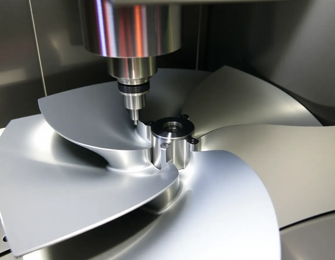
Understanding the "how" begins with the geometry of an impeller. An impeller consists of a central hub with a series of blades (or vanes) radiating outward. These blades are often undercut, meaning they have surfaces that are not accessible from a direct top-down approach. The channels between the blades are deep, narrow, and twisted. Machining this with a 3-axis machine would require numerous setups, complex fixtures, and long, inefficient tool paths with sub-optimal cutting angles, leading to poor surface finish, potential tool breakage, and dimensional inaccuracy.
The Symphony of Simultaneous Movement
5-axis machining solves this by enabling simultaneous 5-axis movement. The machine can tilt and rotate the workpiece or the cutting tool to maintain the optimal cutting orientation relative to the complex surface being machined. For an impeller blade, this means the tool can remain tangent to the blade surface at all points, drastically improving cutting conditions. This is typically achieved through two primary machine configurations:
- Table-Table Configuration: The workpiece is mounted on a table that can tilt (A-axis) and rotate (C-axis). This is excellent for smaller impellers.
- Head-Table or Trunnion Configuration: The tool head tilts (B-axis) while the table rotates (C-axis). This offers greater flexibility for larger, heavier workpieces.
- Head-Head Configuration: Both rotational axes are on the head, allowing for machining of very large parts on a stationary table.
The Machining Workflow: From Blank to Balanced Rotor
The process typically follows a staged approach. It begins with a solid block of high-performance material, such as titanium, Inconel, or aluminum. Roughing operations use robust tools to quickly remove the bulk of material, defining the basic hub and blade channels. Semi-finishing then prepares the near-net shape. The critical finishing stage is where 5-axis capabilities shine. Using specialized tapered ball-nose end mills, the machine follows complex tool paths that constantly adjust the tool orientation to perfectly mill the blade surfaces, leading and trailing edges, and fillets. Finally, deburring and balancing complete the component.
The Tangible Benefits: Why 5-Axis is Non-Negotiable
The adoption of 5-axis machining for impellers is driven by a compelling array of benefits that directly impact performance, cost, and innovation.
Unmatched Precision and Surface Integrity
By allowing the tool to cut at a consistent, optimal angle, 5-axis machining produces superior surface finishes and tighter geometric tolerances. This precision is critical for aerodynamic and hydrodynamic efficiency. Smother blade surfaces reduce friction and turbulence, directly translating to higher performance and energy savings in the final application.
Dramatic Reductions in Lead Time
Single-setup machining is perhaps the most significant advantage. Completing an entire impeller in one clamping eliminates errors accumulated from multiple setups and saves massive amounts of time. Furthermore, shorter, more rigid tools can be used because the head can be tilted to reach deep cavities, allowing for higher feed rates and deeper cuts without sacrificing stability.
Complexity Without Compromise
5-axis machining enables the production of designs that were previously impossible or prohibitively expensive to make. This includes impellers with blades that are closer together (higher blade density), more aggressive twist angles, and integrated features. It liberates engineers to design for peak fluid dynamics without being constrained by manufacturing limitations.
Enhanced Tool Life and Reliability
Constant optimal cutting orientation prevents tool deflection, reduces vibration, and avoids rubbing on the tool's non-cutting surfaces. This leads to more consistent cutting forces, less heat generation, and significantly longer tool life, reducing costs and machine downtime.
Critical Applications and Industries
The demand for precision-machined impellers spans industries where performance and reliability are paramount.
- Aerospace & Defense: Jet engine compressors and turbines, auxiliary power units (APUs), and missile fuel pumps. Materials like titanium and nickel-based superalloys are standard here.
- Automotive & Motorsport: High-performance turbocharger impellers, where reduced inertia and perfect balance are crucial for rapid boost response and engine efficiency.
- Oil & Gas: Multistage compressors and pumps for pipeline transport, refinery processes, and LNG handling, often machined from corrosion-resistant alloys.
- Power Generation: Steam turbines, gas turbines, and cooling pumps for nuclear and thermal power plants.
- Marine & Naval: Propulsion pumps, water jet impellers, and shipboard compressor systems.
Best Practices for Mastering the Process
Achieving speed and precision in 5-axis impeller machining is not automatic; it requires a disciplined approach encompassing technology, software, and skill.
Advanced CAM Software is the Brain
The tool paths for a 5-axis impeller are extraordinarily complex. Specialized CAM software with dedicated impeller machining modules is essential. This software must generate collision-free tool paths, manage tool orientation to avoid gouging, and provide smooth transitions to ensure high surface quality. Simulation within the CAM system is non-negotiable to visually verify the entire process before a single chip is cut.
Machine Tool and Tooling Integrity
The machine itself must be rigid, with high dynamic accuracy and minimal thermal growth. Spindle speed and torque are vital for handling the tough materials often used. Equally important is the tooling: using balanced, high-quality tapered ball-nose end mills with specialized coatings (like AlTiN for high-temperature alloys) is critical for finish and longevity.
Strategic Process Planning
Effective machining starts with a robust plan. This includes:
- Stock Preparation: Ensuring the blank is accurately sized and securely fixtured to withstand high cutting forces.
- Tool Path Strategy: Employing a mix of roughing, semi-finishing, and multiple finishing passes. Using trochoidal or plunge milling for roughing can be highly efficient.
- Cutting Data Optimization: Carefully selecting spindle speeds, feed rates, and depth of cut based on material, tooling, and desired finish. High-speed machining (HSM) techniques are often employed.
- In-Process Verification: Using probe systems to check critical dimensions between operations can prevent costly errors.
The Human Element: Skilled Programmers and Operators
Even with the most advanced technology, the expertise of the programmer and machine operator is irreplaceable. Understanding the interplay between tool geometry, machine kinematics, material behavior, and cutting physics is what separates a functional part from a masterpiece. Continuous training and a mindset of problem-solving are key assets.
Conclusion: The Future of Rotational Power
5-axis impeller machining stands as a testament to the incredible synergy between digital design and physical manufacturing. It is the enabling technology that allows us to push the boundaries of fluid dynamics, thermal efficiency, and mechanical power. By mastering the simultaneous control of speed and precision, manufacturers can produce impellers that are lighter, stronger, and more efficient than ever before. As materials evolve and designs grow more sophisticated, the role of 5-axis machining will only become more central, continuing to drive innovation in every field that relies on moving air and liquid to power our world.